# Control Practices
# Horizontal Speed Control
### General
Speed control is one of the most desirable ways to achieve or maintain a desired separation between aircraft. In general, it results in the smallest increase in controller workload and is particularly useful when sequencing aircraft (such as towards a TMA entry point).
The primary variable affecting the future position, and consequently, separation between aircraft is ground speed. However, it is generally impractical to instruct aircraft to maintain a certain ground speed. Therefore, speed assignments are made with reference to indicated airspeed (IAS) or Mach number.
### Use of horizontal speed control
Speeds may be used to:
Adjust separation (different speeds applied between aircraft)
Maintain separation (the same speed applied between aircraft)
Absorb delay by reducing speed enroute (as an alternative to holding)
Avoid or reduce vectoring:
As an alternative to vectoring
In combination with vectoring to reduce the number and magnitude of heading changes required
### Considerations
#### Applying speed control
Most jet turbine aircraft will be unable to quickly increase or decrease speed, especially at higher altitude, so due consideration must be given to the time taken for an aircraft to reach a desired speed. In certain cases, the speed control may need to be applied, one or two miles prior to when the desired spacing is achieved.
Due consideration must also be given to prevailing winds aloft, as a headwind will decrease an aircraft’s ground speed and a tailwind will increase an aircraft’s ground speed. This may affect the magnitude of the speed instruction that is given to an aircraft.
#### Aircraft performance characteristics
Speeds in excess of the maximum or minimum speeds shall not be assigned to aircraft. Due consideration must be given to the performance characteristics of different aircraft. This ensures that aircraft do not operate too close to high speed/low-speed buffet regions of the flight envelope, especially for aircraft at higher levels (FL350 and above). (See Table 7-1)
Aircraft category
Safe operating Mach
Maximum IAS (below FL250)
SUPER (A380)
0.82 – 0.87
330
HEAVY (B747, B787, A350)
0.82 – 0.87
330
HEAVY (B777, B767, A330, MD11)
0.81 – 0.85
320
MEDIUM (A320, B737)
0.75 – 0.79
300
Table 2-1: Safe operating speed and Mach number ranges
#### Speed control during climb or descent
Instructions for aircraft to maintain a high rate of descent and a low speed, or a high rate of climb and high speed, are generally incompatible.
When aircraft are instructed to increase speed during a climb or decrease speed during a descent, they can be expected to maintain a short period of level or near-level flight in order to comply with the speed instruction. Conversely, when aircraft are instructed to reduce speed during a climb or increase speed during a descent, they can be expected to increase their rate of climb or descent, respectively.
#### Effectiveness
Speed control generally takes more time to achieve the desired separation as compared to other techniques such as vectoring, so due consideration must also be given to the volume of airspace available to achieve the desired separation.
The longer the controller waits before applying speed control, the more drastic the speed change needs to be in order to achieve the desired separation at the handover point. Should this be the case, the controller should revert to vectoring to achieve separation.
#### Relationship between Mach number and true airspeed
When aircraft are flown with reference to Mach number, the true airspeed of an aircraft will decrease with increasing altitude. This must be considered when applying Mach number control between aircraft at different flight levels, as aircraft at higher levels will be flying slower than those at lower levels despite reporting the same Mach number.
#### Relationship between indicated airspeed and true airspeed
When aircraft are being flown with reference to indicated airspeed, their true airspeed will increase with increasing altitude. Therefore, aircraft at higher altitude will be flying faster than those at lower altitude, despite reporting the same indicated airspeed.
#### Mach/airspeed crossover
Aircraft climbing under speed control should be given a Mach number to maintain during the crossover point between indicated airspeed and Mach number to ensure that they maintain a safe operating margin and do not unexpectedly increase speed during the climb.
Conversely, descending aircraft should be given an indicated airspeed to maintain during the crossover, so their speed does not continue to increase as the aircraft descends.
### Rules of thumb
- 0.01 Mach = 6 knots
- Speed difference of 6 knots gives 1 NM of separation change every 10 minutes
- Speed difference of 30 knots gives 1 NM of separation change every 2 minutes
- Speed difference of 60 knots gives 1 NM of separation change every minute
- True airspeed (TAS) = Indicated airspeed (IAS) + 6 knots per 1000 ft above MSL
# Vectoring
### General
Vectoring is achieved by instructing aircraft to maintain a heading that will result in it following a desired ground track. It is one of the most effective techniques to establish and maintain horizontal separation between traffic and is far more effective than speed control in doing so, producing the desired result much more quickly. However, it results in a larger increase in controller as compared to other methods.
When aircraft are placed on a vector, they must be informed of the reason for the vector, and the expected point where they are expected to re-join the flight planned route.
The procedures laid down in 5.2 shall apply when aircraft are under radar vectors.
### Use of vectoring
#### Navigation assistance
Should aircraft navigational equipment fail, or ground navigational aids are unavailable, vectoring may be used to provide navigational assistance to aircraft.
This may also be used to provide navigational assistance to VFR aircraft should they become lost.
#### Circumnavigating airspace
If aircraft is approaching special use airspace such as danger, restricted and prohibited areas and a climb or descent is unfeasible, aircraft may be vectored around the airspace.
#### Conflict prevention
In situations where there is adequate separation between aircraft projected to cross each other at the same level, but it is only slightly above separation minima, aircraft may be instructed to “MAINTAIN PRESENT HEADING”.
This technique of “locking” the heading ensures that the minimum separation will be maintained between aircraft, and the aircraft will not make any turns such as to follow an airway or terminal procedure.
#### Conflict solving
If a level change is not possible, or practical, aircraft may be issued a heading change in order to ensure horizontal separation minima is maintained. In most cases, only a relatively small change in heading is required to achieve the desired result. This results in a minimal change to the aircraft’s total flight distance and therefore to its fuel consumption.
After the conflict has been solved and separation is assured aircraft may be instructed to resume their own navigation.
#### Sequencing
Aircraft may be sequenced to a sector boundary point using a combination of speeds and vectors. The objective of sequencing is to establish and maintain a minimum separation between the leading and following aircraft.
### Vectoring geometry
#### Conflict geometry
##### Crossing point
The crossing point is the point where the projected flight paths between two aircraft are expected to cross. It is fairly easy to determine the crossing point as it is only dependent on the projected tracks of two aircraft and is unaffected by speed and wind.
##### Closest point of approach (CPA)
The minimum distance between two aircraft at the time they pass each other is known as the closest point of approach (CPA). In general, the separation between two aircraft continues to reduce after the first aircraft crosses the track of the second aircraft until reaching the CPA.
CPA is dependent on the angle of the trajectories of the two aircraft and their projected ground speed and therefore the time taken to reach the crossing point. For this reason, it is more complex to calculate than crossing point as it requires the use of trigonometry.
Closest point of approach is displayed on the radar screen along the projected path of an aircraft and is color coded yellow. A red color code indicates that the CPA is below the required separation minima. It should be noted, however that this is an instantaneous prediction and may not necessarily be accurate if aircraft vertical and horizontal speed change and should therefore be used with caution.
##### Determining CPA
- A crossing angle of 90 degrees means separation will be reduced by 30% between crossing point and CPA. As a result, a separation of 7.2 NM at the crossing point is required to ensure 5 NM separation at CPA.
- A crossing angle of 60 degrees means separation will be reduced by 20% between crossing point and CPA. As a result, a separation of 6.3 NM at the crossing point is required to ensure 5 NM separation at the CPA.
- A crossing angle of 60 degrees means separation will be reduced by 10% between crossing point and CPA. As a result, a separation of 5.6 NM is required at the crossing point to ensure 5 NM separation at the CPA.
- A crossing angle of 120 degrees means separation will be reduced by 50% between the crossing point and the CPA. As a result, a separation of 10 NM is required at the crossing point to ensure 5 NM separation at the CPA.
- A crossing angle of 150 degrees means separation will be reduced by 75% between the crossing point and CPA. As a result, a separation of 20 NM is required at the crossing point to ensure 5 NM separation at the CPA.
#### Selecting the aircraft
##### Vectoring both aircraft
This is the most commonly used method to solve conflicts on reciprocal tracks. Although it increases controller workload, as multiple transmissions need to be made to different aircraft, it has less of an impact on each aircraft’s trajectory resulting in a minimal increase in distance flown. For this technique to work, both aircraft need to alter course in the same direction (e.g., both turn mright).
##### Vectoring the aircraft behind
This method is used when two aircraft are maintaining altitude and one is overtaking the other. The aircraft further from the crossing point is given a vector to increase separation. This is much more effective than vectoring the aircraft closer to the crossing point.
##### Vectoring the aircraft requesting a level change
If accommodating a climb or descent request would cause and aircraft to pass through the level of another and subsequently result in insufficient separation between them, the aircraft requesting the level change is usually the one that is given the vector.
This is usually done in three steps, first a vector is given to establish lateral separation between the two aircraft, followed by a vector to parallel the track, while at the same time accommodating the climb request. Once the aircraft has passed through the level of the other with sufficient vertical separation, a direct routing is given to the requesting aircraft to re-establish it on the planned track.
##### More complex situations
In more complex situations where the aforementioned techniques would not necessarily, generally controllers should follow the principle of requiring minimal intervention to achieve the desired result.
#### Turn direction
##### Aircraft on reciprocal tracks
Aircraft on opposing tracks should be vectored in the direction that would increase separation
##### Aircraft on crossing tracks
The aircraft further away from the crossing point should be “aimed” at the current position of the aircraft closer to the crossing point. This results in the distance from the crossing point of the leading aircraft to be reduced significantly, where the distance from the crossing point of the second aircraft is only marginally reduced. This method causes the second aircraft to pass behind the first.
For example, if the aircraft further from the crossing point has traffic on the left-hand side, it should be turned to the left to “aim” it towards the crossing traffic. Although it may seem counter-intuitive, this method will increase the separation between the aircraft.
##### Aircraft on the same track requesting a level change
The requesting aircraft should be turned into the wind, which will result in a reduction in its ground speed, resulting in a larger rate of increase of separation and placing the aircraft being vectored further behind. A sufficiently strong wind can be much more effective than speed control in managing an aircraft’s speed.
##### Consideration of the planned track
When aircraft are being vectored, due consideration must also be given to the planned flight paths of the aircraft such that the vector does not result in a significant increase in the track miles flown by the aircraft. In this case, aircraft may be issued a direct routing to “cut the corner”, which will have the same effect as a vector in that direction.
##### Airspace consideration
The dimensions of the airspace must also be considered when issuing vectors to aircraft. Aircraft shall not be vectored closer than 2.5 NM to the boundary of the airspace that a controller is responsible for, as this may require other actions such as coordination and further conflict solving.
#### Crossing angle
After the direction of turn is selected, the extent of the heading change must be determined. The crossing angle is crucial as it determines:
The increase of separation after vectoring
The separation reduction between the crossing point and the CPA The general impact of the crossing angle is as follows:
Right angle (crossing) tracks allows the 1-in-60 rule to be used
Acute angle (similar) tracks lead to:
Less separation gained be vectoring as opposed to other options. This scenario may sometimes require a heading change of 20 degrees or more, and if wind conditions are unfavorable, it may require an even greater turn.
In combination with vectoring to reduce the number and magnitude of heading changes required
Obtuse angle (reciprocal) tracks lead to:
Greater separation reduction after the crossing point
More separation gained by vectoring. A small turn of 5 to 10 degrees is often enough to achieve the desired separation.
### Associated risks
#### Forgetting that an aircraft has been issued a vector
This has a negative impact on flight efficiency and may also “surprise” the next controller if the airway or arrival procedure makes a sharp turn at the transfer point and the aircraft does not.
To mitigate this risk, the aircraft tag is marked before handoff to the next controller when the aircraft is placed under radar vectors.
#### Miscalculation of wind impact
If a controller attempts to sequence an aircraft behind another and by turning but instructs the aircraft to turn so the tailwind increases, the maneuver may have no effect as the tailwinds increases the aircraft’s speed effectively reducing the expected benefit from vectoring.
In addition, the wind speed and direction may be different at different levels and may vary significantly. Consequently, the headwind/tailwind/crosswind component will also vary, affecting the desired result. For example, the drift angle may be different at different levels, resulting in aircraft flying on converging tracks despite flying parallel headings.
This may be mitigated by assigning slightly diverging headings to aircraft being vectored.
#### Miscalculation of aircraft performance
Generally climbing aircraft increase their ground speed and descending aircraft will reduce their ground speed. The speed at cruise level may be up to twice as high as the speed at lower altitudes.
To mitigate this risk, controllers must always have an awareness of the performance characteristics that are altered by changes in altitude.
### Rules of thumb
- Turn radius in NM = Ground speed in knots / 100
# Level Change
### General
During various phases of flight, level changes by aircraft may be necessary for the purpose of separation.
When issuing a level change clearance, vertical and horizontal separation between aircraft shall always be assured. Controllers must ensure that the cleared level will not result in a loss of separation with any other traffic in the vicinity prior to issuing a level clearance.
Due consideration be given to aircraft on crossing or reciprocal tracks, as well as aircraft that are on the same track which may be separated vertically but may not have adequate horizontal separation.
If there is any doubt as to whether separation will be assured an alternative clearance must be provided.
### Level change clearance
#### Climb clearance
During a climb, when an aircraft is expected to cross, or is on the same track as proximate traffic and separation may reduce to below minimum horizontal separation, they shall only be cleared:
- To a level 1000 ft below traffic that is maintaining level flight; or
- To a level vacated by traffic if its mode C readout indicates a climb; or
- To a level 1000 ft below the clearance level of traffic that is descending
#### Descent clearance
During a descent, when an aircraft is expected to cross, or is on the same track as proximate traffic and separation may reduce to below minimum horizontal separation, they shall only be cleared:
- To a level 1000 ft above traffic that is maintaining level flight; or
- To a level vacated by traffic if its mode C readout indicates a descent; or
- To a level 1000 ft above the clearance level of traffic that is climbing
#### Horizontal speed control in combination with a level clearance
For two or more aircraft on the same track, the level clearance requirements in 9.2.2, and 9.2.3 may be exempted provided horizontal speed control has been applied and appropriate minimum horizontal separation exists and will continue to exist.
#### Vertical speed control in combination with a level clearance
For aircraft on crossing tracks, the requirements in 9.2.2 and 9.2.3 may be exempted, provided adequate vertical speed control has been applied and adequate horizontal separation exists and will continue to exist throughout the level change maneuver.
### Associated risks
#### Incorrect altimeter setting
An incorrect altimeter setting between QNH and standard pressure may result in a loss of separation between aircraft at transition level and transition altitude. To mitigate this risk, an additional buffer shall be used between transition altitude and level.
#### Confusion between altitude and flight level
Often, confusion may occur between the terms “ALTITUDE” and “FLIGHT LEVEL”. In order to mitigate this risk, controllers must be vigilant when listening to a read back of the cleared level when transitioning between altimeter settings and reiterate the clearance and pass the QNH if necessary.
#### Level busts
Aircraft maintaining a very high rate of climb or descent may overshoot the cleared level in some circumstances. If aircraft are expected to maintain a high rate or climb descent, an additional buffer of vertical separation may be required in order to ensure that a level bust will not result in a loss of mseparation.
### Rules of thumb
- Aircraft will lose approximately 300 ft per 1 NM travelled forward during descent
- Aircraft need 10 NM to lose 3000 ft
- Aircraft need 16 NM to lose 5000 ft
- Aircraft need 33 NM to lose 10,000 ft
- A tailwind will increase descent track miles required; a headwind will decrease descent track miles required.
- If a rapid descent is required, aircraft should be instructed to maintain a high airspeed and then reduce speed during level flight.
# Vertical Speed Control
### General
Vertical speed is a useful method of maintaining separation between aircraft that are climbing or
descending. Aircraft may be instructed to maintain a specific climb or descent rate. This is most useful
when aircraft are climbing or descending through the level of other aircraft or are descending in a
holding pattern.
### Application of vertical speed control
Vertical speed control may be applied:
- To accommodate climb requests (by requesting an aircraft to expedite passing a level)
- For separation of arriving and departing traffic in opposite directions
- To descend arriving aircraft below enroute traffic
- For vertical sequencing between climbing or descending aircraft
- For corrective action (when unrestricted vertical speed is insufficient)
### Benefits
#### Efficiency
Effectively used vertical speed control allows for continuous climbs and descents and therefore better efficiency. In addition, it permits descents to start close to top of descent and allows timely accommodation of climb and descent requests.
#### Reduced controller workload
This method also ensures vertical separation is maintained, resulting in reduced workload because of a reduced need for vectoring and/or horizontal speed control.
### Risks
#### Reduced separation
The margin for error is reduced as this method relies on maintaining minimum vertical separation, which is much lower than minimum horizontal separation, therefore any non-compliance may result in a loss of separation between aircraft.
#### Non-compliance or misunderstanding
A misunderstanding of the instruction may result in the desired separation not being achieved. A correct readback does not guarantee compliance.
Aircraft may be unable to maintain the assigned rate of climb or descent beyond a certain level. If this
occurs, there is a possibility the flight crew may not inform the controller.
### Considerations
#### Aircraft performance
Certain aircraft types such as the Airbus A321 and Airbus A340 are unable to maintain high rates of climb.
In addition, climb rates can be expected to decrease when aircraft are approaching their cruise level, and will therefore generally be unable to maintain rates of climb in excess of 1000 ft/min. High temperatures will further reduce this value.
High rates of descent are generally incompatible with low airspeeds. Instructions to maintain both a high descent rate and low speed should be avoided.
Aircraft autopilots generally take a few seconds to respond. The transition time to achieve a vertical rate should be taken into account when issuing vertical speed control.
#### Level busts
When aircraft are within 2000 to 3000 ft of their assigned level, they should not be instructed to maintain vertical speeds in excess of 1500 ft/min in order to avoid a level bust and to prevent possible TCAS RA activation.
#### Safety buffer
In order to mitigate the risk of traffic on reciprocal tracks losing separation a safety buffer of one or two minutes needs to be applied by issuing the clearance earlier or assigning a higher vertical speed to maintain.
#### Expedited climbs or descents
The phrases “EXPEDITE CLIMB” and “EXPEDITE DESCENT” do not specify vertical speeds and should be used with caution. Climbing aircraft will climb at the maximum rate possible, which may sometimes be insufficient to achieve the desired result. The use of safety margins and alternative clearances should therefore be considered.
Aircraft descending will generally increase their vertical speed to 2000 ft/min or greater when instructed to expedite. For this reason, it is advisable that this instruction is given early on in the descent.
#### Alternative clearance
Controllers must always have an alternative plan available to accommodate a climb or descent request if aircraft are unable to comply with a vertical speed instruction.
### Rules of thumb
- A vertical speed of 2000 ft/min results in a change of 10 flight levels in 5 minutes
- A vertical speed of 2500 ft/min results in a change of 10 flight levels in 4 minutes
- A combined vertical speed of 4000 ft/min (such as when one aircraft is climbing and the other is descending), results in a change of 20 flight levels in 5 minutes
# Holding
### General
Holding is an instrument procedure employed by ATC as a delay tactic to manage the rate of traffic flow into a terminal area, to ensure that its capacity is not exceeded during peak arrival times, as well as times when traffic flow rate is constrained such as during low visibility or single-runway operations.
Holding is generally managed by area control, and aircraft are instructed to hold at fixes that are\\ outside the respective terminal area. In exceptional cases, holding may be conducted within the terminal area at published holding fixes on the respective STAR.
During times of peak arrivals, a dedicated holding stack controller is often used to reduce the workload of the area controller and allow more efficient level allocation and timely hold exits.
### Hold capacity
All holding fixes have a maximum holding capacity that is determined by the minimum and maximum holding levels. When the hold’s maximum capacity is reached, i.e., aircraft are entering the hold at levels above the maximum holding level, aircraft shall be instructed to proceed to an alternative holding fix.
### Hold management
#### Hold entry
Aircraft shall generally enter the hold via one of three entry procedures:
- Parallel entry (sector 1)
- Offset/teardrop entry (sector 2)
- Direct entry (sector 3 )
##### Hold entry sectors:
[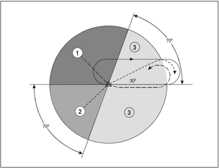](https://docs.vatsim.ma/uploads/images/gallery/2025-03/icao-hold-entry.png)
Aircraft that have reported entering the hold may be considered established over the holding fix.
#### Descent clearance
When aircraft are instructed to descend in the hold, they shall only be cleared:
- To a level 1000 ft above traffic below that is maintaining level flight; or
- To a level vacated by traffic below if its mode C readout indicates a descent
#### Hold exit
Once aircraft are ready to be sequenced for the arrival, they should be instructed to exit the hold. There are three primary methods of instructing an aircraft to exit the hold, each with their own set of risks and benefits.
##### Exit on completion of hold
This technique allows aircraft to be given the hold exit instruction in advance when radio traffic permits. However, this does not allow for an expeditious exit from the hold and may sometimes take up to 5 minutes to accomplish the hold instruction. This means that the exit must be planned for in advance, potentially increasing controller workload.
To accomplish this, aircraft must be instructed “ON COMPLETION, EXIT THE HOLD”.
##### Exit with a direct
For an immediate exit, aircraft may be instructed to proceed directly to the holding fix from their present position. This allows for an exit from the hold requiring a maximum of 2 minutes to accomplish. However, this method is liable to error from a mis-programmed FMC.
In order to mitigate this risk, it is preferable to instruct the aircraft to proceed directly to the first fix on the STAR instead of the holding fix. This guarantees that the aircraft will not remain in the hold, as they will bypass the holding fix.
An additional advantage of this technique is that aircraft remain within the holding protected area under most circumstances.
##### Vectored exit in combination with a direct
Vectors used in combination with instructions to proceed directly to a fix allow for an expeditious hold exit and has many advantages, as it allows the aircraft to be immediately taken out of the hold and establishes horizontal separation with holding traffic. This allows the holding traffic to be descended to a lower altitude provided that the exiting traffic is kept at minimum radar separation from holding traffic.
To accomplish this, aircraft are issued an appropriate vector to either extend the outbound heading, or to fly a heading that is perpendicular to the holding inbound course towards the non-holding side. A combination of both these headings may be used to exit multiple aircraft simultaneously.
Once aircraft have been vectored clear of holding traffic, they may be given a direct to either the holding fix or to the first fix on the STAR. Consideration shall be given to the risks discussed in 6 .3.3.2.
The minimum holding level is above the highest minimum sector altitude and assures terrain and obstacle clearance. However, as with any other time when vectoring an aircraft, consideration shall be given to the minimum radar maneuvering altitudes, as well as adjacent airspace.