Operational Context
Introduction
Definitions and abbreviations
ADS-B. Automatic dependent surveillance – broadcast. A means by which aircraft can automatically transmit and/or receive data such as identification, position and additional data, as appropriate, in a broadcast mode via datalink.
Air traffic flow management (ATFM). A service established with the objective of contributing to a safe, orderly and expeditious flow of air traffic by ensuring that ATC capacity is utilized to the maximum extent possible, and that the traffic volume is compatible with the capacities declared by the appropriate ATS authority.
ATIS. Automatic terminal information service, the automatic provision of current, routine information to arriving and departing aircraft.
Ceiling. The height above the ground or water of the base of the lowest layer of cloud below 20, feet covering more than half the sky.
Dependent parallel approaches. Simultaneous approaches to parallel or near-parallel instrument runways where radar separation minima between aircraft of adjacent extended runway centerlines are prescribed.
Independent parallel approaches. Simultaneous approaches to parallel or near-parallel instrument runways where radar separation minima between aircraft of adjacent extended runway centerlines are not prescribed.
Independent parallel departures. Simultaneous departures from parallel or near-parallel runways.
Maneuvering area. The part of an aerodrome used for take-off, landing, and taxiing of aircraft excluding aprons.
Multilateration (MLAT) system. A group of equipment configured to provide position derived from secondary surveillance radar (SSR) transponder reply signals primarily using time difference of arrival techniques. Additional information, including identification, can be extracted from the signals.
Near-parallel runways. Non-intersecting runways whose extended centerlines have an angle of convergence or divergence of 15 degrees or less.
Standard instrument arrival (STAR). A designated instrument flight rule (IFR) arrival route linking a significant point, normally on an ATS route, to a point from which a published instrument approach procedure can be commenced.
Standard instrument departure (SID). A designated instrument flight rule (IFR) departure route linking the aerodrome, or a specific runway on the aerodrome with a significant point, normally on a designated ATS route, at which the enroute phase of flight commences.
Role of air traffic services
Air traffic services (ATS) primarily exist to expedite and maintain a safe and orderly flow of traffic. ATS ensures that collisions are prevented between aircraft, and between aircraft and other objects on the aerodrome surface.
ATS comprises of several services including flight information service, alerting service (for search and rescue), air traffic advisory service, and air traffic control service. Air traffic control service includes area control service, controlling larger sectors of airspace when aircraft are enroute, approach control service which is responsible for separating and sequencing aircraft in the terminal area, and aerodrome control service which manages aircraft on or in the vicinity of an aerodrome.
General Provisions
Altimeter setting procedures
Altimetry
Aircraft maintain their level primarily with reference to a calibrated barometer, known as an altimeter, that is set to a specified pressure setting. As atmospheric pressure decreases with altitude, measuring the pressure outside the hull of an aircraft can provide a means to measure its altitude.
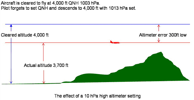
Altimeters are calibrated to the ISA standard atmosphere and will indicate an increase in altitude of approximately 30 ft for every 1 hPa reduction in atmospheric pressure near sea level. Barometric altimeters only measure the altitude above the reference pressure setting and have no means of indicating an aircraft’s true altitude, so some adjustment is required for different atmospheric conditions to ensure that the indicated level is accurate.
Air traffic controllers must pass the required pressure setting information to an aircraft, based on its location and level above ground. This is important as aircraft with different or inappropriate altimeter settings will be flying at different true altitudes and may result in a loss of separation with other aircraft or with terrain.
Altitude
When aircraft are being flown with reference to a local pressure setting, or QNH, the level is expressed as an altitude in thousands of feet above mean sea level. QNH corrects for local pressure deviations and provides aircraft with an indication of their height above mean sea level.
For example, the level of an aircraft that is at an indicated altitude of 8000 ft with reference to QNH, would be expressed as an altitude of 8000 ft.
Altitudes are typically flown at lower levels, usually within the aerodrome terminal area where terrain separation becomes a factor. Altitudes can be quickly measured against known elevation of the surrounding terrain, which is important during the approach and landing phase.
Flight level
When aircraft are being flown with reference to the standard barometric pressure setting, the level is expressed as a Flight Level (FL), in multiples of 100 ft.
For example, the level of an aircraft at an indicated altitude of 36000 ft with reference to standard barometric pressure, it would be said to be cruising at Flight Level 360 (FL 360).
Typically, aircraft are flown at flight levels during cruise. This is done to avoid several altimeter setting changes as aircraft travel long distances where atmospheric conditions are different. During cruise, terrain separation is rarely a factor, and separation between aircraft is more important.
Ensuring all enroute aircraft are following the same altimeter setting simplifies the controller’s task of separating as aircraft as two aircraft at the same place will always have the same altimeter error.
Transition altitude and transition level
Due to the nature of aircraft altimeters, when transitioning from QNH to standard pressure, there will be an error in the reading, especially when atmospheric conditions are different from standard. This error may mean that aircraft following QNH may not be separated from aircraft following standard pressure at the adjacent higher level.
In order to avoid this problem, a transition altitude and transition level are established by each local ATS authority that ensure that minimum vertical separation will exist between aircraft referencing QNH and standard pressure.
The transition altitude is the highest available altitude to an aircraft with reference to QNH, whereas the transition level is the lowest available flight level (with reference to standard pressure).
The area between the transition altitude and transition level is known as the transition layer. Sustained flight within this layer must be avoided as adequate vertical separation may not be assured between aircraft.
Horizontal speed control
Airspeed
The airspeed of an aircraft is expressed in knots and, like barometric altitude, is subject to errors. Indicated airspeed is the uncorrected airspeed displayed to the flight crew and is an indication of “how much air” the aircraft is hitting at a given moment.
When a speed restriction is assigned to an aircraft for the purposes of separation, it will be with reference to indicated airspeed (IAS). Speed assignments must be applied in multiples of 10 knots.
True airspeed (TAS) is the true rate of movement of the aircraft through the airmass at a given time, corrected for instrument, pressure, compressibility and density error.
TAS rises by approximately two per cent for every 1000 ft an aircraft climbs when compared to IAS. For the purposes of ATC, however, to estimate an aircraft’s true airspeed, approximately 6 knots may be added to the aircraft’s reported indicated airspeed per every 1000 ft of altitude. Below 8000 ft, the difference between indicated and true airspeed is not significant and may be neglected.
In addition, controllers must also have an awareness of the current wind conditions, as a tailwind will result in an increased ground speed and a headwind will have the opposite effect.
Mach number
At higher altitudes, the effects of compressibility become the overriding factor in jet turbine aircraft aerodynamics. Because of this, Mach number is primary reference used to measure airspeed and any adjustments are applied in increments of 0.01 Mach.
For ATC speed control, Mach numbers are used above FL250.
Application of speed control
In order to facilitate orderly flow of traffic, ATC must provide aircraft with adequate notice of any speed control to be provided.
Speed instructions should be limited to those necessary to maintain adequate separation. Frequent alternating increases and decreases in speed should be avoided.
In order to maintain desired spacing, however, speed instructions should be issued to all aircraft concerned.
For aircraft entering or established in a holding pattern, speed control instructions must not be issued.
Descending and arriving aircraft
Arriving aircraft should, wherever possible, be permitted to absorb a period of terminal delay by cruising at a reduced speed before entry into a terminal hold. Instructions for aircraft to maintain “minimum clean speed” (the minimum speed of an aircraft with flaps and gear retracted) may be used for this purpose.
Other instructions to maintain “maximum speed” or “minimum speed” nay also be used to apply separation.
Speed reductions to less than 250 knots during the initial descent from cruising level of jet turbine aircraft should be avoided unless coordinated with pilots.
In addition, aircraft should not be instructed to maintain high rates of descent as well as to reduce speed simultaneously, as most aircraft will be unable to achieve this. Aircraft that are instructed to slow down during descent can be expected to maintain a short period of level or near-level flight to reduce speed.
Unless otherwise required by the terminal procedure or for traffic separation purposes, aircraft shall be permitted to operate in clean configuration for as long as possible below FL 150. The minimum clean speed for most jet turbine aircraft is approximately 220 knots. Speed reductions below this would require the use of flaps or slats.
Approach phase
During the intermediate and final approach phase, speed changes exceeding 20 knots must not be applied.
Controllers must be aware that aircraft must achieve a stabilized approach by 1000 ft above aerodrome level (AAL). As such speed control inside 4 nautical miles from touchdown should be avoided.
In addition, instructions to maintain speeds greater than 160 knots within an 8 nautical mile final should be avoided.
Vertical speed control
In order to maintain a safe and organized flow of traffic, aircraft can be instructed to adjust their climb and descent rates. This may be applied to two climbing aircraft or two descending aircraft to ensure adequate vertical separation exists.
Aircraft in a climb shall be issued a vertical speed greater than or equal to a specific value, or less than or equal to a specified value. The same method applies for aircraft in a descent.
In addition, aircraft can be instructed to expedite their rate of climb or descent through a specific level, or to reduce their rate of climb or descent.
Vertical speed control should only be assigned as necessary to ensure separation and frequent changes to climb/descent rates should be avoided.
When no longer needed, aircraft should be informed that vertical speed control has been cancelled.
Vertical speed control is expressed in “feet per minute” and in multiples of 100.
Aviation Law
Classification of Airspace
ATS airspace is classified and designated in accordance with the following:
Class A. IFR flights only are permitted, all flights are provided with air traffic control service and are separated from each other.
Class B. IFR and VFR flights are permitted, all flights are provided with air traffic control service and are separated from each other.
Class C. IFR and VFR flights are permitted, all flights are provided with air traffic control service and IFR flights are separated from other IFR flights and from VFR flights. VFR flights are separated from IFR flights and receive traffic information in respect of other VFR flights.
Class D. IFR and VFR flights are permitted and all flights are provided with air traffic control service, IFR flights are separated from other IFR flights and receive traffic information in respect of VFR flights, VFR flights receive traffic information in respect of all other flights.
Class E. IFR and VFR flights are permitted, IFR flights are provided with air traffic control service and are separated from other IFR flights. All flights receive traffic information as far as is practical. Class E shall not be used for control zones.
Class F. IFR and VFR flights are permitted, all participating IFR flights receive an air traffic advisory service and all flights receive flight information service if requested.
Class G. IFR and VFR flights are permitted and receive flight information service if requested.
The services provided and flight requirements for different classes of airspace are shown in the table below.
| Class | Type of Flight | Separation Provided | Service Provided | Speed Limitation | Radio Communication Requirement | Subject to ATC Clearance |
|---|---|---|---|---|---|---|
| A | IFR only | All aircraft | Air traffic control service | Not applicable | Continuous two-way | Yes |
| B | IFR | All aircraft | Air traffic control service | Not applicable | Continuous two-way | Yes |
| B | VFR | All aircraft | Air traffic control service | Not applicable | Continuous two-way | Yes |
| C | IFR | IFR from IFR, IFR from VFR | Air traffic control service | Not applicable | Continuous two-way | Yes |
| C | VFR | VFR from IFR | 1) Air traffic control service for separation from IFR 2) VFR/VFR traffic information service (and traffic avoidance advice on request) | 250 kts IAS below 10000 ft amsl | Continuous two-way | Yes |
| D (1) | IFR | IFR from IFR | Air traffic control service, traffic information about VFR flights (and traffic avoidance advice on request) | 250 kts IAS below 10000 ft amsl | Continuous two-way | Yes |
| D (1) | VFR | Nil | IFR/VFR and VFR/VFR traffic information (and traffic avoidance advice on request) | 250 kts IAS below 10000 ft amsl | Continuous two-way | Yes |
| E (2) | IFR | IFR from IFR | Air traffic control service and, as far as practical, traffic information about VFR flights | 250 kts IAS below 10000 ft amsl | Continuous two-way | Yes |
| E (2) | VFR | Nil | Traffic information as far as practical | 250 kts IAS below 10000 ft amsl | No | No |
| F | IFR | IFR from IFR as far as practical | Air traffic advisory service; flight information service | 250 kts IAS below 10000 ft amsl | Continuous two-way | No |
| F | VFR | Nil | Flight information service | 250 kts IAS below 10000 ft amsl | No | No |
| G | IFR | Nil | Flight information service | 250 kts IAS below 10000 ft amsl | Continuous two-way | No |
| G | VFR | Nil | Flight information service | 250 kts IAS below 10000 ft amsl | No | No |
Important Notes:
(1): In Class D airspace, both IFR and VFR traffic are required to follow ATC clearances; however, ATC are only responsible for IFR against IFR separation.
(2): In Class E airspace, ATC does not provide separation between IFR and VFR traffic; IFR traffic shares responsibility for separation from uncontrolled VFR traffic with that traffic.
Altimeter
The aircraft altimeter barometric sub-scale must be set to the appropriate setting for the phase of flight. These are:
- Flight level. Standard pressure setting (1013 hPa) is set when flying by reference to flight levels at or above the transition level;
- Altitude. Regional or airfield pressure setting (QNH) is set when flying by reference to altitude above mean sea level at or below the transition altitude;
- Height. Altimeter pressure setting indicating height above airfield or touchdown (QFE) is set when approaching to land at airfield where this procedure is in use. Note that this setting is not used in other portions of the flight (climb, cruise and initial descent).
Aircraft are not supposed to fly level within the transition layer (between the transition altitude and the transition level). When passing through it, their vertical position is expressed in:
- flight levels during climb (i.e. above the transition altitude)
- altitudes during descent (i.e. below the transition level)
If no transition altitude and transition level are defined (which is common for en-route flights outside the TMAs), the vertical position of aircraft shall be expressed in terms of:
- flight levels at or above the lowest usable flight level
- altitudes below the lowest usable flight level
Failure to set the appropriate barometric sub-scale pressure setting may result in a significant deviation from the cleared altitude or Flight Level
Aircraft Knowledge
Aircraft Description
ICAO Doc 8643 provides data on aircraft such as the Manufacturer, Model, Type designator, etc. One of the items is called Description and is a three-symbol code containing basic data about the aircraft:
- The first symbol describes the aircraft type:
- L - Landplane, e.g. A320. Note: A floatplane, which can temporarily be converted to a landplane or vice versa, is described as a landplane and not a seaplane or amphibian in ICAO Doc 8643.
- S - Seaplane, e.g. HARBIN SH-5 (ICAO designator SH5)
- A - Amphibian, e.g. LA4
- G - Gyrocopter, e.g. A002
- H - Helicopter, e.g. A109
- T - Tiltrotor, e.g. V22
- The second symbol specifies the number of engines 1, 2, 3, 4, 6, 8 or C, where C means that two engines are coupled to drive a single propeller system (e.g. C08T). The C symbol is only used for fixed-wing aircraft.
- The third symbol specifies the engine type:
- J - jet
- T - turboprop/turboshaft
- P - piston
- E - electric
- R - rocket
Examples
- L2J - a landplane with two jet engines
- H2T - a helicopter with two turboprop/turboshaft engines
- S1P - a seaplane with one piston engine
ICAO Aerodrome Reference Code
The ICAO Aerodrome Reference Code is a two part categorisation of aircraft types which simplifies the process of establishing whether a particular aircraft is able to use a particular aerodrome. It is included in ICAO Annex 14. It has two 'elements', the first is a numeric code based on the Reference Field Length for which there are four categories and the second is letter code based on a combination of aircraft wingspan and outer main gear wheel span.
Element 1 of the Code is as follows:
| Code number | Aeroplane reference field length | Typical aeroplane |
|---|---|---|
| 1 | < 800 m | DE HAVILLAND CANADA DHC-6/PIPER PA-31 |
| 2 | 800 m but < 1200 m | ATR ATR-42-300/320/BOMBARDIER Dash 8 Q300 |
| 3 | 1200 m but < 1800 m | SAAB 340/BOMBARDIER Regional Jet CRJ-200 |
| 4 | 1800 m and above | BOEING 737-700/AIRBUS A-320 |
Field length means the balanced field length (which is when the take-off distance required is equal to the accelerate-stop distance required) if applicable, or take-off distance in other cases. Aeroplane reference field length is defined as "the minimum field length required for take-off at maximum certificated take-off mass, at sea level, in International Standard Atmosphere conditions in still air and with zero runway slope as documented in the Aircraft Flight Manual (AFM) or equivalent document.
Element 2 of the Code is derived from the most restrictive of either the aircraft wingspan or the aircraft outer main gear wheel span. The categories are as follows:
| Code letter | Wingspan | Typical aeroplane |
|---|---|---|
| A | < 15 m | PIPER PA-31/CESSNA 404 Titan |
| B | 15 m but < 24 m | BOMBARDIER Regional Jet CRJ-200/DE HAVILLAND CANADA DHC-6 |
| C | 24 m but < 36 m | BOEING 737-700/AIRBUS A-320/EMBRAER ERJ 190-100 |
| D | 36 m but < 52 m | B767 Series/AIRBUS A-310 |
| E | 52 m but < 65 m | B777 Series/B787 Series/A330 Family |
| F | 65 m but < 80 m | BOEING 747-8/AIRBUS A-380-800 |
It should be noted that Element 2 is often used on its own since it has direct relevance to detailed airport design. It also has a parallel but differently defined code use by the FAA, the Airplane Design Group (ADG)
Wake Turbulence Category
The ICAO wake turbulence category (WTC) is entered in the appropriate single character wake turbulence category indicator in Item 9 of the ICAO model flight plan form and is based on the maximum certificated take-off mass, as follows:
- J (Super) aircraft types specified as such in Doc 8643 (Aircraft type designators). At present, the only such type is the Airbus A380-800 with a maximum take-off mass in the order of 560 000 kg. (see Airbus A380 Wake Vortex Guidance)
- H (Heavy) aircraft types of 136 000 kg (300 000 lb) or more (except those specified as J);
- M (Medium) aircraft types less than 136 000 kg (300 000 lb) and more than 7 000 kg (15 500 lb); and
- L (Light) aircraft types of 7 000 kg (15 500 lb) or less.
Variants of an aircraft type may fall into different wake turbulence categories, (e.g. L/M or M/H). In these cases, it is the responsibility of the pilot or operator to enter the appropriate wake turbulence category indicator in the flight plan.