GEN
- Operational Context
- Separation
- ATS Surveillance Services
- Separation Methods and Minima
- Separation in the Vicinity of Aerodromes
- Radar Separation
- Wake Turbulence Separation
- Runway Separation
- Visual Separation
- Procedural Control
- Control Practices
- Aerodrome Control
- Approach Control
Operational Context
Introduction
Definitions and abbreviations
ADS-B. Automatic dependent surveillance – broadcast. A means by which aircraft can automatically transmit and/or receive data such as identification, position and additional data, as appropriate, in a broadcast mode via datalink.
Air traffic flow management (ATFM). A service established with the objective of contributing to a safe, orderly and expeditious flow of air traffic by ensuring that ATC capacity is utilized to the maximum extent possible, and that the traffic volume is compatible with the capacities declared by the appropriate ATS authority.
ATIS. Automatic terminal information service, the automatic provision of current, routine information to arriving and departing aircraft.
Ceiling. The height above the ground or water of the base of the lowest layer of cloud below 20, feet covering more than half the sky.
Dependent parallel approaches. Simultaneous approaches to parallel or near-parallel instrument runways where radar separation minima between aircraft of adjacent extended runway centerlines are prescribed.
Independent parallel approaches. Simultaneous approaches to parallel or near-parallel instrument runways where radar separation minima between aircraft of adjacent extended runway centerlines are not prescribed.
Independent parallel departures. Simultaneous departures from parallel or near-parallel runways.
Maneuvering area. The part of an aerodrome used for take-off, landing, and taxiing of aircraft excluding aprons.
Multilateration (MLAT) system. A group of equipment configured to provide position derived from secondary surveillance radar (SSR) transponder reply signals primarily using time difference of arrival techniques. Additional information, including identification, can be extracted from the signals.
Near-parallel runways. Non-intersecting runways whose extended centerlines have an angle of convergence or divergence of 15 degrees or less.
Standard instrument arrival (STAR). A designated instrument flight rule (IFR) arrival route linking a significant point, normally on an ATS route, to a point from which a published instrument approach procedure can be commenced.
Standard instrument departure (SID). A designated instrument flight rule (IFR) departure route linking the aerodrome, or a specific runway on the aerodrome with a significant point, normally on a designated ATS route, at which the enroute phase of flight commences.
Role of air traffic services
Air traffic services (ATS) primarily exist to expedite and maintain a safe and orderly flow of traffic. ATS ensures that collisions are prevented between aircraft, and between aircraft and other objects on the aerodrome surface.
ATS comprises of several services including flight information service, alerting service (for search and rescue), air traffic advisory service, and air traffic control service. Air traffic control service includes area control service, controlling larger sectors of airspace when aircraft are enroute, approach control service which is responsible for separating and sequencing aircraft in the terminal area, and aerodrome control service which manages aircraft on or in the vicinity of an aerodrome.
General Provisions
Altimeter setting procedures
Altimetry
Aircraft maintain their level primarily with reference to a calibrated barometer, known as an altimeter, that is set to a specified pressure setting. As atmospheric pressure decreases with altitude, measuring the pressure outside the hull of an aircraft can provide a means to measure its altitude.
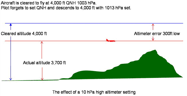
Altimeters are calibrated to the ISA standard atmosphere and will indicate an increase in altitude of approximately 30 ft for every 1 hPa reduction in atmospheric pressure near sea level. Barometric altimeters only measure the altitude above the reference pressure setting and have no means of indicating an aircraft’s true altitude, so some adjustment is required for different atmospheric conditions to ensure that the indicated level is accurate.
Air traffic controllers must pass the required pressure setting information to an aircraft, based on its location and level above ground. This is important as aircraft with different or inappropriate altimeter settings will be flying at different true altitudes and may result in a loss of separation with other aircraft or with terrain.
Altitude
When aircraft are being flown with reference to a local pressure setting, or QNH, the level is expressed as an altitude in thousands of feet above mean sea level. QNH corrects for local pressure deviations and provides aircraft with an indication of their height above mean sea level.
For example, the level of an aircraft that is at an indicated altitude of 8000 ft with reference to QNH, would be expressed as an altitude of 8000 ft.
Altitudes are typically flown at lower levels, usually within the aerodrome terminal area where terrain separation becomes a factor. Altitudes can be quickly measured against known elevation of the surrounding terrain, which is important during the approach and landing phase.
Flight level
When aircraft are being flown with reference to the standard barometric pressure setting, the level is expressed as a Flight Level (FL), in multiples of 100 ft.
For example, the level of an aircraft at an indicated altitude of 36000 ft with reference to standard barometric pressure, it would be said to be cruising at Flight Level 360 (FL 360).
Typically, aircraft are flown at flight levels during cruise. This is done to avoid several altimeter setting changes as aircraft travel long distances where atmospheric conditions are different. During cruise, terrain separation is rarely a factor, and separation between aircraft is more important.
Ensuring all enroute aircraft are following the same altimeter setting simplifies the controller’s task of separating as aircraft as two aircraft at the same place will always have the same altimeter error.
Transition altitude and transition level
Due to the nature of aircraft altimeters, when transitioning from QNH to standard pressure, there will be an error in the reading, especially when atmospheric conditions are different from standard. This error may mean that aircraft following QNH may not be separated from aircraft following standard pressure at the adjacent higher level.
In order to avoid this problem, a transition altitude and transition level are established by each local ATS authority that ensure that minimum vertical separation will exist between aircraft referencing QNH and standard pressure.
The transition altitude is the highest available altitude to an aircraft with reference to QNH, whereas the transition level is the lowest available flight level (with reference to standard pressure).
The area between the transition altitude and transition level is known as the transition layer. Sustained flight within this layer must be avoided as adequate vertical separation may not be assured between aircraft.
Horizontal speed control
Airspeed
The airspeed of an aircraft is expressed in knots and, like barometric altitude, is subject to errors. Indicated airspeed is the uncorrected airspeed displayed to the flight crew and is an indication of “how much air” the aircraft is hitting at a given moment.
When a speed restriction is assigned to an aircraft for the purposes of separation, it will be with reference to indicated airspeed (IAS). Speed assignments must be applied in multiples of 10 knots.
True airspeed (TAS) is the true rate of movement of the aircraft through the airmass at a given time, corrected for instrument, pressure, compressibility and density error.
TAS rises by approximately two per cent for every 1000 ft an aircraft climbs when compared to IAS. For the purposes of ATC, however, to estimate an aircraft’s true airspeed, approximately 6 knots may be added to the aircraft’s reported indicated airspeed per every 1000 ft of altitude. Below 8000 ft, the difference between indicated and true airspeed is not significant and may be neglected.
In addition, controllers must also have an awareness of the current wind conditions, as a tailwind will result in an increased ground speed and a headwind will have the opposite effect.
Mach number
At higher altitudes, the effects of compressibility become the overriding factor in jet turbine aircraft aerodynamics. Because of this, Mach number is primary reference used to measure airspeed and any adjustments are applied in increments of 0.01 Mach.
For ATC speed control, Mach numbers are used above FL250.
Application of speed control
In order to facilitate orderly flow of traffic, ATC must provide aircraft with adequate notice of any speed control to be provided.
Speed instructions should be limited to those necessary to maintain adequate separation. Frequent alternating increases and decreases in speed should be avoided.
In order to maintain desired spacing, however, speed instructions should be issued to all aircraft concerned.
For aircraft entering or established in a holding pattern, speed control instructions must not be issued.
Descending and arriving aircraft
Arriving aircraft should, wherever possible, be permitted to absorb a period of terminal delay by cruising at a reduced speed before entry into a terminal hold. Instructions for aircraft to maintain “minimum clean speed” (the minimum speed of an aircraft with flaps and gear retracted) may be used for this purpose.
Other instructions to maintain “maximum speed” or “minimum speed” nay also be used to apply separation.
Speed reductions to less than 250 knots during the initial descent from cruising level of jet turbine aircraft should be avoided unless coordinated with pilots.
In addition, aircraft should not be instructed to maintain high rates of descent as well as to reduce speed simultaneously, as most aircraft will be unable to achieve this. Aircraft that are instructed to slow down during descent can be expected to maintain a short period of level or near-level flight to reduce speed.
Unless otherwise required by the terminal procedure or for traffic separation purposes, aircraft shall be permitted to operate in clean configuration for as long as possible below FL 150. The minimum clean speed for most jet turbine aircraft is approximately 220 knots. Speed reductions below this would require the use of flaps or slats.
Approach phase
During the intermediate and final approach phase, speed changes exceeding 20 knots must not be applied.
Controllers must be aware that aircraft must achieve a stabilized approach by 1000 ft above aerodrome level (AAL). As such speed control inside 4 nautical miles from touchdown should be avoided.
In addition, instructions to maintain speeds greater than 160 knots within an 8 nautical mile final should be avoided.
Vertical speed control
In order to maintain a safe and organized flow of traffic, aircraft can be instructed to adjust their climb and descent rates. This may be applied to two climbing aircraft or two descending aircraft to ensure adequate vertical separation exists.
Aircraft in a climb shall be issued a vertical speed greater than or equal to a specific value, or less than or equal to a specified value. The same method applies for aircraft in a descent.
In addition, aircraft can be instructed to expedite their rate of climb or descent through a specific level, or to reduce their rate of climb or descent.
Vertical speed control should only be assigned as necessary to ensure separation and frequent changes to climb/descent rates should be avoided.
When no longer needed, aircraft should be informed that vertical speed control has been cancelled.
Vertical speed control is expressed in “feet per minute” and in multiples of 100.
Aviation Law
Classification of Airspace
ATS airspace is classified and designated in accordance with the following:
Class A. IFR flights only are permitted, all flights are provided with air traffic control service and are separated from each other.
Class B. IFR and VFR flights are permitted, all flights are provided with air traffic control service and are separated from each other.
Class C. IFR and VFR flights are permitted, all flights are provided with air traffic control service and IFR flights are separated from other IFR flights and from VFR flights. VFR flights are separated from IFR flights and receive traffic information in respect of other VFR flights.
Class D. IFR and VFR flights are permitted and all flights are provided with air traffic control service, IFR flights are separated from other IFR flights and receive traffic information in respect of VFR flights, VFR flights receive traffic information in respect of all other flights.
Class E. IFR and VFR flights are permitted, IFR flights are provided with air traffic control service and are separated from other IFR flights. All flights receive traffic information as far as is practical. Class E shall not be used for control zones.
Class F. IFR and VFR flights are permitted, all participating IFR flights receive an air traffic advisory service and all flights receive flight information service if requested.
Class G. IFR and VFR flights are permitted and receive flight information service if requested.
The services provided and flight requirements for different classes of airspace are shown in the table below.
| Class | Type of Flight | Separation Provided | Service Provided | Speed Limitation | Radio Communication Requirement | Subject to ATC Clearance |
|---|---|---|---|---|---|---|
| A | IFR only | All aircraft | Air traffic control service | Not applicable | Continuous two-way | Yes |
| B | IFR | All aircraft | Air traffic control service | Not applicable | Continuous two-way | Yes |
| B | VFR | All aircraft | Air traffic control service | Not applicable | Continuous two-way | Yes |
| C | IFR | IFR from IFR, IFR from VFR | Air traffic control service | Not applicable | Continuous two-way | Yes |
| C | VFR | VFR from IFR | 1) Air traffic control service for separation from IFR 2) VFR/VFR traffic information service (and traffic avoidance advice on request) | 250 kts IAS below 10000 ft amsl | Continuous two-way | Yes |
| D (1) | IFR | IFR from IFR | Air traffic control service, traffic information about VFR flights (and traffic avoidance advice on request) | 250 kts IAS below 10000 ft amsl | Continuous two-way | Yes |
| D (1) | VFR | Nil | IFR/VFR and VFR/VFR traffic information (and traffic avoidance advice on request) | 250 kts IAS below 10000 ft amsl | Continuous two-way | Yes |
| E (2) | IFR | IFR from IFR | Air traffic control service and, as far as practical, traffic information about VFR flights | 250 kts IAS below 10000 ft amsl | Continuous two-way | Yes |
| E (2) | VFR | Nil | Traffic information as far as practical | 250 kts IAS below 10000 ft amsl | No | No |
| F | IFR | IFR from IFR as far as practical | Air traffic advisory service; flight information service | 250 kts IAS below 10000 ft amsl | Continuous two-way | No |
| F | VFR | Nil | Flight information service | 250 kts IAS below 10000 ft amsl | No | No |
| G | IFR | Nil | Flight information service | 250 kts IAS below 10000 ft amsl | Continuous two-way | No |
| G | VFR | Nil | Flight information service | 250 kts IAS below 10000 ft amsl | No | No |
Important Notes:
(1): In Class D airspace, both IFR and VFR traffic are required to follow ATC clearances; however, ATC are only responsible for IFR against IFR separation.
(2): In Class E airspace, ATC does not provide separation between IFR and VFR traffic; IFR traffic shares responsibility for separation from uncontrolled VFR traffic with that traffic.
Altimeter
The aircraft altimeter barometric sub-scale must be set to the appropriate setting for the phase of flight. These are:
- Flight level. Standard pressure setting (1013 hPa) is set when flying by reference to flight levels at or above the transition level;
- Altitude. Regional or airfield pressure setting (QNH) is set when flying by reference to altitude above mean sea level at or below the transition altitude;
- Height. Altimeter pressure setting indicating height above airfield or touchdown (QFE) is set when approaching to land at airfield where this procedure is in use. Note that this setting is not used in other portions of the flight (climb, cruise and initial descent).
Aircraft are not supposed to fly level within the transition layer (between the transition altitude and the transition level). When passing through it, their vertical position is expressed in:
- flight levels during climb (i.e. above the transition altitude)
- altitudes during descent (i.e. below the transition level)
If no transition altitude and transition level are defined (which is common for en-route flights outside the TMAs), the vertical position of aircraft shall be expressed in terms of:
- flight levels at or above the lowest usable flight level
- altitudes below the lowest usable flight level
Failure to set the appropriate barometric sub-scale pressure setting may result in a significant deviation from the cleared altitude or Flight Level
Aircraft Knowledge
Aircraft Description
ICAO Doc 8643 provides data on aircraft such as the Manufacturer, Model, Type designator, etc. One of the items is called Description and is a three-symbol code containing basic data about the aircraft:
- The first symbol describes the aircraft type:
- L - Landplane, e.g. A320. Note: A floatplane, which can temporarily be converted to a landplane or vice versa, is described as a landplane and not a seaplane or amphibian in ICAO Doc 8643.
- S - Seaplane, e.g. HARBIN SH-5 (ICAO designator SH5)
- A - Amphibian, e.g. LA4
- G - Gyrocopter, e.g. A002
- H - Helicopter, e.g. A109
- T - Tiltrotor, e.g. V22
- The second symbol specifies the number of engines 1, 2, 3, 4, 6, 8 or C, where C means that two engines are coupled to drive a single propeller system (e.g. C08T). The C symbol is only used for fixed-wing aircraft.
- The third symbol specifies the engine type:
- J - jet
- T - turboprop/turboshaft
- P - piston
- E - electric
- R - rocket
Examples
- L2J - a landplane with two jet engines
- H2T - a helicopter with two turboprop/turboshaft engines
- S1P - a seaplane with one piston engine
ICAO Aerodrome Reference Code
The ICAO Aerodrome Reference Code is a two part categorisation of aircraft types which simplifies the process of establishing whether a particular aircraft is able to use a particular aerodrome. It is included in ICAO Annex 14. It has two 'elements', the first is a numeric code based on the Reference Field Length for which there are four categories and the second is letter code based on a combination of aircraft wingspan and outer main gear wheel span.
Element 1 of the Code is as follows:
| Code number | Aeroplane reference field length | Typical aeroplane |
|---|---|---|
| 1 | < 800 m | DE HAVILLAND CANADA DHC-6/PIPER PA-31 |
| 2 | 800 m but < 1200 m | ATR ATR-42-300/320/BOMBARDIER Dash 8 Q300 |
| 3 | 1200 m but < 1800 m | SAAB 340/BOMBARDIER Regional Jet CRJ-200 |
| 4 | 1800 m and above | BOEING 737-700/AIRBUS A-320 |
Field length means the balanced field length (which is when the take-off distance required is equal to the accelerate-stop distance required) if applicable, or take-off distance in other cases. Aeroplane reference field length is defined as "the minimum field length required for take-off at maximum certificated take-off mass, at sea level, in International Standard Atmosphere conditions in still air and with zero runway slope as documented in the Aircraft Flight Manual (AFM) or equivalent document.
Element 2 of the Code is derived from the most restrictive of either the aircraft wingspan or the aircraft outer main gear wheel span. The categories are as follows:
| Code letter | Wingspan | Typical aeroplane |
|---|---|---|
| A | < 15 m | PIPER PA-31/CESSNA 404 Titan |
| B | 15 m but < 24 m | BOMBARDIER Regional Jet CRJ-200/DE HAVILLAND CANADA DHC-6 |
| C | 24 m but < 36 m | BOEING 737-700/AIRBUS A-320/EMBRAER ERJ 190-100 |
| D | 36 m but < 52 m | B767 Series/AIRBUS A-310 |
| E | 52 m but < 65 m | B777 Series/B787 Series/A330 Family |
| F | 65 m but < 80 m | BOEING 747-8/AIRBUS A-380-800 |
It should be noted that Element 2 is often used on its own since it has direct relevance to detailed airport design. It also has a parallel but differently defined code use by the FAA, the Airplane Design Group (ADG)
Wake Turbulence Category
The ICAO wake turbulence category (WTC) is entered in the appropriate single character wake turbulence category indicator in Item 9 of the ICAO model flight plan form and is based on the maximum certificated take-off mass, as follows:
- J (Super) aircraft types specified as such in Doc 8643 (Aircraft type designators). At present, the only such type is the Airbus A380-800 with a maximum take-off mass in the order of 560 000 kg. (see Airbus A380 Wake Vortex Guidance)
- H (Heavy) aircraft types of 136 000 kg (300 000 lb) or more (except those specified as J);
- M (Medium) aircraft types less than 136 000 kg (300 000 lb) and more than 7 000 kg (15 500 lb); and
- L (Light) aircraft types of 7 000 kg (15 500 lb) or less.
Variants of an aircraft type may fall into different wake turbulence categories, (e.g. L/M or M/H). In these cases, it is the responsibility of the pilot or operator to enter the appropriate wake turbulence category indicator in the flight plan.
Separation
ATS Surveillance Services
General Procedures
Aircraft identification
For aircraft to be provided ATS surveillance services, aircraft identification must be established, and the pilot informed. Identification should then be maintained until the termination of ATS surveillance.
Identification on a secondary surveillance radar system (SSR) is established by one of the following methods:
- Recognition of the setting of a discrete transponder code (i.e., not ending in 00)
- Observation of the IDENT feature of an aircraft transponder where a discrete transponder code has already been assigned.
Once radar identification has been established the pilot shall be informed. If at any time identification is lost or ATS surveillance service terminated, this pilot shall also be informed.
Position information
Where identification has been performed the aircraft should be informed of its position except in the following cases:
- Transfer of identification from one controller to another; or
- Assigned discrete SSR code identification and the aircraft’s position is consistent with its expected position based on its flight plan; or
- Based on the pilot’s report of position or within 1 NM of the departure runway and consistent with the planned departure time of the aircraft.
Position information shall be passed in the following forms:
- As a well-known geographical location; or
- As a magnetic track and distance from a significant point, enroute navigational aid or approach aid; or
- Direction (using points of a compass) from a known position; or
- Distance to touchdown if the aircraft is on final approach; or
- Distance and direction from the centerline of an ATS route.
Wherever practical, position information shall be made with reference to positions or routes relevant to the aircraft concerned.
Radar vectoring
Vectoring is achieved by assigning aircraft specific headings which will enable the aircraft to maintain the desired track.
When vectoring an aircraft, controllers should comply with the following:
- When an aircraft is given its initial vector diverting it from a previously assigned route, the pilot shall be informed of what the vector is to accomplish, and the limit of the vector should be specified (e.g., to position for approach).
- Controlled flights shall not be vectored into uncontrolled airspace except in case of emergency or to avoid adverse meteorological conditions, or on the specific request of the pilot.
When vectoring an IFR flight and when giving an IFR flight a direct routing which takes the aircraft off an ATS route, the controller should ensure that the minimum obstacle clearance exists at all times until the aircraft reaches a point where it is able to resume its own navigation.
When radar vectors are terminated, the controller shall issue an appropriate instruction to the aircraft to return it to its pre-planned route, and the aircraft should be instructed to resume own navigation.
Application of separation
Separation shall only be applied with reference to ATS surveillance systems if there is reasonable assurance that identification of aircraft will be obtained and maintained.
When the control of an identified aircraft will be transferred to a sector that applies procedural separation, or a higher separation minima, this separation must be applied before the aircraft enters the next sector, or the sector of airspace where the higher separation minima applies.
Under no circumstances should the symbols on the radar screen touch or overlap unless vertical separation is assured.
Separation minima based on ATS surveillance
SSR/ADS-B/MLAT based separation minima
When aircraft are under ATS surveillance either from SSR, ADS-B or MLAT, the minimum horizontal separation is 5.0 NM.
This may be reduced to 3.0 NM when radar and/or ADS-B and MLAT systems capabilities at a given location permit.
Separation minima on final approach
A minimum separation of 2.5 NM may be applied between aircraft under ATS surveillance when established on the final approach course within 10 NM of the runway threshold provided:
- The average runway occupancy of aircraft is not more than 50 seconds; and
- Braking action is reported as good and runway occupancy times are not adversely affected by contaminants such as slush, ice, and snow; and
- The aerodrome controller is able to observe visually or by means of surface movement radar or surface movement guidance and control (SMGCS), the runway in use and exit and entry taxiways; and
- Distance based wake turbulence minima do not apply; and
- Aircraft approach speeds are closely monitored by the controller and adjusted where necessary to ensure minimum separation; and
- Aircraft operators and pilots have been made fully aware of the need to exit the runway in an expeditious manner at the assigned exit taxiway
Separation from adjacent airspace
Except where transfer of control to be made, aircraft shall not be vectored closer than 2.5 NM to the boundary of the airspace that a controller is responsible for unless there has been prior coordination with the controller of the adjacent sector. This ensures that minimum horizontal separation will always exist between aircraft in different sectors.
Distance-based wake turbulence separation minima
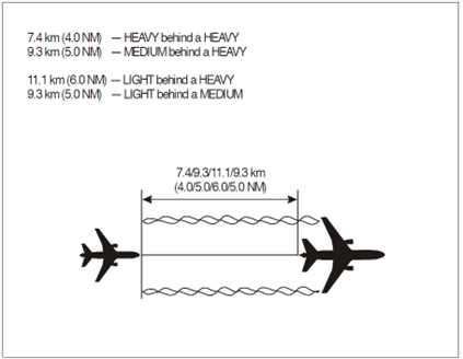
The following distance-based wake turbulence separation minima shall by applied when aircraft are under ATS surveillance during the approach and departure phases of flight.
These minima shall be applied under the following circumstances:
- An aircraft is operating directly behind another at the same altitude or less than 1000 ft below; or
- Both aircraft are using the same runway, or a parallel runway separated by less than 760 meters; or
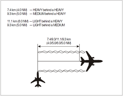
- An aircraft is crossing behind another aircraft at the same altitude or less than 1000 ft below
| Preceding Aircraft Category Succeeding Aircraft Category Separation Minima | Succeeding Aircraft Category | Separation Minima |
|---|---|---|
| SUPER | ||
| HEAVY | 6 NM | |
| MEDIUM | 7 NM | |
| LIGHT | 8 NM | |
| HEAVY | ||
| HEAVY | 4 NM | |
| MEDIUM | 5 NM | |
| LIGHT | 6 NM | |
| MEDIUM | LIGHT | 5 NM |
Aircraft operating directly behind:
Aircraft crossing behind:
Separation from aircraft that are holding
Where vertical separation does not exist between aircraft established in a holding pattern and aircraft not holding, a minimum of 5.0 NM of horizontal separation must exist.
Separation of aircraft on reciprocal tracks
Where confirmation has been obtained from radar derived that aircraft on reciprocal tracks have passed, there is no requirement to ensure that minimum radar separation exists before reducing the minimum vertical separation provided:
- Both aircraft are properly identified; and
- Radar label leader lines for both tracks are not crossed; and
- The distance between the position symbols is increasing; and
- The position symbols are not touching or overlapping
Verification of Mode C altitude readout
Verification of pressure-altitude-derived level information Mode C displayed to the controller shall be affected by simultaneous comparison (reported and observed at least once on initial contact by the first controller providing a surveillance service), when an aircraft enters civil controlled airspace after departure from an aerodrome.
Following successful verification, the Mode C information may be considered to remain verified provided it is associated with a Mode A SSR Code that has been previously validated by another controller and that the observed Mode C information has an error of 200ft or less at all levels.
Determination of level occupancy
Maintaining a level
An aircraft may be considered to be maintaining a level when the observed altitude readout is within the tolerances, of the assigned level.
Vacating a level
An aircraft can be considered to have vacated a level during a climb or descent when the observed altitude readout is more than 200ft from the previously occupied level, in the anticipated direction.
Passing a level
An aircraft may be considered to have crossed a level during a climb or descent when the observed altitude readout has passed the level by more than 200ft in the required direction.
Reaching a level
An aircraft may be considered to have reached a level to which it had been cleared when whichever is the greater of 3 sensor or display updates, or 15 seconds has passed since the level information has indicated that it is within the appropriate tolerance.
Departing a runway
Aircraft may be considered to have departed a runway when the surveillance display indicates a positive rate of climb from the aerodrome elevation. However, Mode C information shall not be used when the display varies by more than 200ft from the aerodrome elevation during the take-off roll.
Separation Methods and Minima
Separation is required to ensure there is always a minimum distance between aircraft to minimize the risk of collision. This is provided by means of position reports, or by identification on radar.
There are two main types of separation employed by ATC: vertical and horizontal separation. If at any time one type of separation between aircraft is below the prescribed minimum, the other type of separation must exist. For example, if the horizontal separation between aircraft is below minimum, vertical separation must exist.
Vertical and horizontal separation must be provided:
- Between all flights in Class A and B airspace
- Between all IFR flights in Class C, D, and E airspace
- Between IFR and VFR flights in Class C airspace
- Between IFR and special VFR flights
When issuing clearances, the controller must ensure that it would not reduce the separation between aircraft to below the required minima. In addition, if one type of separation minima cannot be maintained, then another type of separation must be applied between aircraft before any separation minima is infringed.
Vertical separation
Vertical separation minima
Vertical separation is assured by assigning aircraft specific altitudes or flight levels in accordance with the altimeter setting procedures described in section 2.1.
Unless subject to the conditions described below, aircraft flying below FL 290 must be separated by a minimum of 1000 ft. Above this level, aircraft must be separated by at least 2000 ft vertically.
Reduced vertical separation minima (RVSM)
Special instrument and equipment installation is required for an aircraft to be able to operate in RVSM airspace. Between FL 290 and FL 410, RVSM may be applied. Most modern turbine aircraft are equipped to operate in RVSM airspace.
Under RVSM, for aircraft flying below FL 410, the minimum vertical separation is 1000 ft. Above this level, a separation minima of 2000 ft is applied.
Assignment of cruising levels
Aircraft will typically be assigned only one cruising level for an aircraft travelling beyond a controller’s control area. It is the responsibility of the next controller to issue further climb as appropriate.
ATC must also ensure that the cruising level is not below the published minimum enroute cruising level for a specified route or airway.
In general, aircraft already occupying a specified cruising level will have priority for that cruising level. For example, when two or more aircraft have requested the same cruising level, the preceding aircraft will normally have priority.
RVSM cruising levels
Cruising levels in RVSM airspace are assigned according to the semi-circular rule (Table 3-1). The semi-circular specifies cruising levels based on an aircraft’s planned magnetic track.
Additionally, any regional level restrictions must also be complied with in conjunction with the semi-circular rule.
Semi-circular rule for aircraft cruising levels

Vertical separation during climb or descent
During a climb or descent, aircraft may only be permitted to initiate a climb or descent to a level previously occupied by another aircraft after the latter has reported vacating that level.
The only exceptions to this rule apply when aircraft are encountering severe turbulence, or their performance is markedly different, such as a lightly loaded 777 following an A320. For these cases, the second aircraft may only be cleared to the level of the fist after it has passed a level separated by the specified minimum.
Consideration must also be given to the vertical speed of aircraft descending in a holding pattern, to ensure that the separation minima is not infringed at any point. If required, ATC should specify minimum or maximum descent rates.
Horizontal separation
Lateral separation
Lateral separation is applied so that the spanwise distance between two aircraft never reduces to below a specified minimum. This is ensured by operating aircraft on different routes at different locations, by visual observation, by, the use of navigational aids or by area navigation (RNAV).
Lateral separation criteria and minima
Lateral separation can be applied through the following methods:
- By reference to position reports which positively indicate aircraft geographical location, visually or by reference to a navigational aid
- By reference to VOR, NDB, or GNSS on intersecting tracks or ATS routes separated by a minimum appropriate to the navigational aid used (Table 3-2)
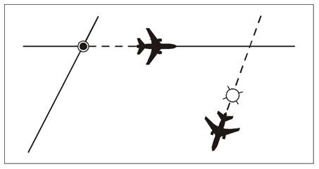
Lateral separation between two aircraft flying VOR or GNSS on crossing tracks:
|
Angular difference between tracks measured at the common point (degrees) |
1000 ft to FL 190 Distance from common point |
FL 200 to FL 600 Distance from common point |
|---|---|---|
|
15 to 135 |
15 NM |
23 NM |
|
The distances given here are ground distances between aircraft |
||
Visual representation of lateral separation based on geographical position:
Longitudinal separation
Longitudinal separation is applied so that the distance between two aircraft never reduces below a prescribed minimum on their longitudinal axis (nose to tail). Longitudinal separation will be applied for aircraft on the same or diverging tracks using speed control.
When applying time or distanced based longitudinal separation, controllers must exercise caution for aircraft with different speed characteristics. If a following aircraft maintains a higher speed than the preceding aircraft, speed control must be applied before aircraft are expected to reach minimum separation.
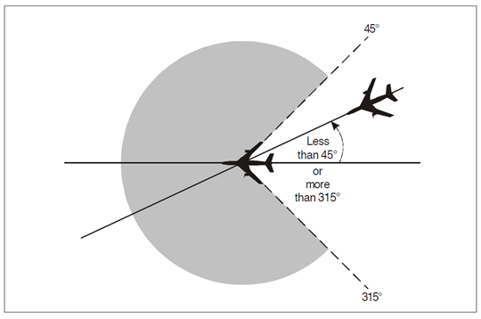
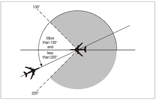
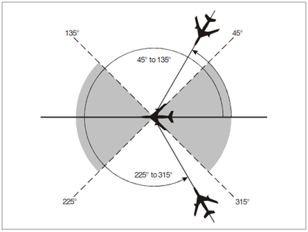
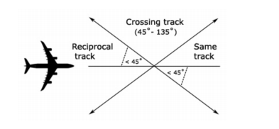
For separation purposes the terms “same track”, “reciprocal track”, and “crossing track” have the following meanings:
Aircraft on the same track:
Aircraft on reciprocal tracks:
Aircraft on crossing tracks:
Longitudinal separation minima based on distance using GNSS or DME
Aircraft maintaining separation with reference to any combination of DME or on board GNSS systems (RNAV) must be in direct contact with ATC though VHF radio.
The following minima applies for this type of separation.
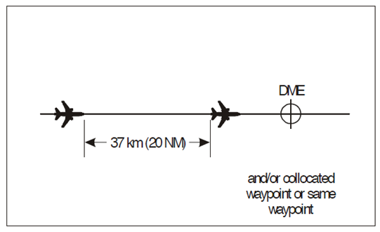
Aircraft at the same level
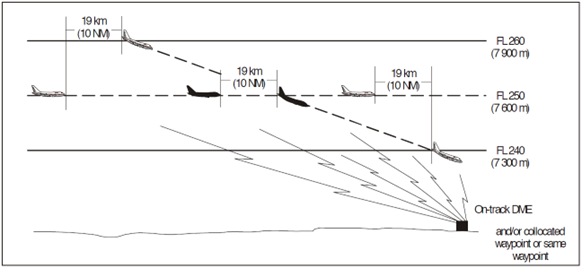
For aircraft at the same level, and following the same track (Figure 3-5) the longitudinal separation minima is 20 NM, provided each aircraft uses the following:
- The same “on track” DME
- An “on track” DME and a collocated waypoint where one aircraft is using DME and the other
- GNSS
- The same waypoint where both aircraft are using GNSS
Separation must be checked by obtaining constant GNSS based or DME based position data at frequent intervals. Aircraft that are ADS-B out capable will satisfy this requirement.
Longitudinal separation for aircraft at the same level on the same track using DME and/or collocated GNSS waypoint:
Reduced longitudinal separation
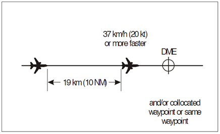
For aircraft at the same level following the same track, the longitudinal separation minima may be reduced to 10 NM, provided the leading aircraft is travelling 20 knots faster or more (Figure 3-6).
The same conditions as 3.2.4.1 will also apply in order to use this reduced separation.
Reduced DME/GNSS based longitudinal separation for aircraft on the same track and at the same level:
Aircraft on crossing tracks
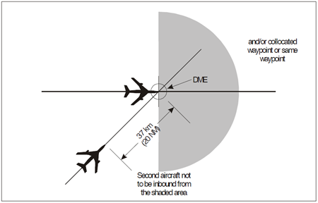
For aircraft on crossing tracks where the relative angle between the tracks is less than 90 degrees, the aircraft shall be separated by a minimum of 20 NM provided each aircraft reports a distance based on DME/collocated GNSS waypoint (Figure 3-7).
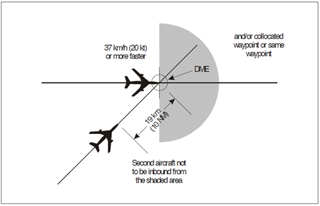
A reduced separation minimum of 10 NM may also be applied if the leading aircraft is travelling 20 knots or faster or more (Figure 3-8).
The same conditions as 4 .2.4.1 shall apply for both these cases.
DME/GNSS based separation for crossing traffic at the same level:
DME/GNSS based reduced separation for crossing traffic at the same level:
Aircraft climbing or descending
The separation minima for aircraft climbing or descending through the level of another following the same track is 10 NM.
In this case, one aircraft must maintain the same level when vertical separation does not exist (Figure 3-9, 3-10).
The same conditions as 4 .2.4.1 also apply.
DME/GNSS based longitudinal separation for aircraft climbing through the level of another on the same track:
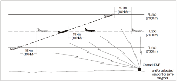
DME/GNSS based longitudinal separation for aircraft descending through the level of another on the same track:
Separation in the Vicinity of Aerodromes
Procedures for departing aircraft
General
At aerodromes where standard instrument departures (SIDs) are established, departing aircraft should normally be cleared to follow an appropriate SID
If no specific procedures are established or aircraft are unable to comply with a SID, the direction of flight after take-off, the initially cleared level and any other necessary information should be passed to the aircraft.
Standard clearances for departing aircraft
Standard clearances for departing aircraft shall contain the following items:
- Aircraft identification;
- Clearance limit, normally the destination aerodrome;
- Designator of the assigned SID, if applicable;
- Cleared level;
- Allocated SSR code;
- Any other necessary instructions or information not contained in the SID description
Clearances on a SID
Where departing aircraft are expected to comply with all speed and altitude restrictions on the SID, the phrase “CLIMB VIA SID TO ” shall be used by the controller.
When departing aircraft is cleared to proceed directly to a published waypoint on the SID, the speed and altitude restrictions associated with the bypassed waypoints are cancelled. All remaining speed and altitude restrictions remain applicable.
When a departing aircraft is vectored or cleared to a point that is not on the SID, all published speed and altitude restrictions on the SID are cancelled. If necessary, the controller shall:
- Reiterate the cleared level
- Provide speed and altitude restrictions as necessary
- Notify the pilot if is expected that the aircraft will be subsequently instructed to re-join the SID and the expected point where this will occur.
Procedures for arriving aircraft
General
At aerodromes where standard instrument arrivals (STARs) have been established, aircraft will normally be cleared to follow the appropriate STAR. The aircraft shall be advised of the type of approach and runway-in-use as early as possible. After coordination with the approach controller, the first aircraft may be cleared for the approach by the area control center controller.
An IFR flight shall not be cleared for an initial approach below the appropriate minimum altitude specified for the procedure unless.
- The pilot has reported passing an appropriate point as define by a navigation aid or as a waypoint; or
- The pilot reports the aerodrome is and can be maintained in sight; or
- The aircraft is conducting a visual approach; or
- The controller has determined the aircraft’s position by the use of an ATS surveillance system and a lower minimum altitude has been established for that sector.
Standard clearances for arriving aircraft
Where standard clearances are in use for arriving aircraft, provided no terminal delay is expected, the area control center may clear an aircraft to follow a STAR without prior coordination with the approach controller.
Provision shall always be made to inform the approach controller of the sequence of aircraft following the same STAR.
Standard clearances for arriving aircraft shall contain the following items:
- Aircraft identification;
- Designator of the assigned STAR if applicable;
- Runway-in-use except where part of the STAR description;
- Cleared level;
- Any other necessary instruction or information not contained in the STAR description
Clearances on a STAR
Where arriving aircraft are expected to comply with all published altitude and speed restrictions on a STAR, the phrase “DESCEND VIA STAR TO ” should be used.
When arriving aircraft are cleared to proceed directly to a published waypoint on the STAR, the speed and altitude restrictions associated with the bypassed waypoints are cancelled. All remaining speed and altitude restrictions remain applicable.
When arriving aircraft are vectored or cleared to a point that is not on the STAR, all published speed and altitude restrictions on the STAR are cancelled. If necessary, the controller shall:
- Reiterate the cleared level; and
- Provide speed and altitude restrictions as necessary; and
- Notify the pilot if is expected that the aircraft will be subsequently instructed to re-join the STAR and the expected point where this will occur.
Visual approach
An IFR aircraft may be cleared to execute a visual approach provided the pilot can maintain visual reference to the terrain and:
- The reported ceiling is at or above the level of the beginning of the relevant initial approach segment; and
- The pilot reports at the level of the beginning of the initial approach segment or at any time during the instrument approach procedure that with the prevailing meteorological conditions there is reasonable assurance that a visual approach and landing can be completed.
Subject to these conditions, clearance for an IFR aircraft to execute a visual approach may be requested by the pilot or initiated by the controller. In the latter case, the flight crew must agree to continue visually.
For successive visual approaches, separation shall be maintained between aircraft by the controller until the pilot of the second aircraft reports having the first aircraft in sight and is able to maintain own separation. Where both aircraft are HEAVY category aircraft or the preceding aircraft is of a heavier category, a caution of possible wake turbulence shall be provided if the distance between them islower than the appropriate wake turbulence minimum.
Instrument approach
The approach controller shall specify the instrument approach procedure to be used by the arriving aircraft. A flight crew may request an alternative approach procedure and, if circumstances permit, should be cleared accordingly.
If visual reference is established before completion of the approach procedure, the entire procedure must be executed unless the aircraft requests and is cleared for a visual approach.
Holding
In the event of extended delays, aircraft should be advised of such delay, and be permitted to reduce speed in order to absorb some of the arrival delay.
When delay is expected the area control center shall normally be responsible for clearing aircraft to the holding fix and for including holding instructions, expected approach time or onward clearance time as applicable.
Operations on parallel runways
Departing aircraft
Types of operation
Parallel runways may be used for independent instrument departures in the following modes:
- Both runways used exclusively for departures (independent departures); or
- One runway is used exclusively for departures while the other is used for a mixture of departures and arrivals (semi-mixed operations); or
- Both runways are used for mixed arrivals and departures (mixed operations)
Requirements and procedures for independent parallel departures
Independent parallel IFR departures may be conducted on parallel runways provided:
- The minimum distance between runway centerlines is at least 760 m; and
- Departure tracks diverge by at least 15 degrees immediately after take-off; and
- A suitable surveillance system capable of identifying aircraft within 1 NM of the runway is available; and
- ATS operational procedures ensure that track separation is achieved.
Arriving aircraft
Types of operation
Parallel runways may be used for simultaneous instrument operations for:
- Independent parallel approaches; or
- Dependent parallel approaches; or
- Segregated parallel approaches
Requirements and procedures for independent parallel approaches
Independent parallel approaches may be conducted provided that:
- The minimum distance between runway centerlines is 1035 meters and suitable ATS surveillance equipment is available such as SSR, MLAT or ADS-B; and
- Instrument landing system (ILS) approaches are being conducted on both runways; and
- The missed approach track for one approach diverges by at least 30 degrees from the missed approach track of the adjacent approach; and
- Aircraft are advised of the runway identification as early as possible; and
- Vectoring is used to intercept the final approach course; and
- A no transgression zone (NTZ) at least 610 meters wide equidistant between runway centerlines must exist and be clearly marked on the radar display; and
- Separate controllers monitor the approaches to each runway and ensure that where 1000 ft vertical separation is reduced, aircraft do not enter the NTZ and applicable longitudinal separation between aircraft on the same localizer course is maintained; and
- Transfer of control is initiated before the higher of the two aircraft has intercepted the glide slope.
- The approach controller has frequency override capability over aerodrome control
As early as possible when aircraft have established communications with the approach controller, aircraft must be informed that independent parallel approaches are in use. This may be done through an ATIS broadcast.
When vectoring to intercept the ILS localizer course, the final vector should allow the aircraft to intercept at an angle of not greater than 30 degrees and allow for at least 1.0 NM of straight and level flight before the localizer intercept. The vector should also enable the aircraft to fly straight and level for at least 2.0 NM after establishing on the localizer before establishing on the glide path.
A minimum of 1000 ft vertical separation or a minimum radar separation of 3.0 NM must be applied between aircraft on parallel approaches until they are established on the final approach course.
For aircraft on the same localizer course, a minimum separation of 3.0 NM shall be applied unless greater longitudinal separation is required for wake turbulence or other reasons.
When assigning the final heading to intercept the ILS localizer course, the runway shall be confirmed and the aircraft shall be advised of:
- Its position relative to a fix on the ILS localizer course; and
- The altitude to be maintained when established on the ILS localizer course until the glide slope intercept point is reached; and
- If required, clearance for the appropriate ILS approach.
When aircraft are observed to overshoot the turn-on or continue on a track that will penetrate the NTZ, aircraft shall be instructed to return immediately to the correct track.
When an aircraft is observed entering the NTZ, the aircraft on the adjacent ILS localizer course shall be immediately instructed to climb and turn to the assigned heading/altitude to avoid the deviating aircraft.
Flight path monitoring shall not be terminated until:
- Visual separation is applied, provided both controllers are advised wherever visual separation is applied;
- The aircraft has landed, or in the case of a missed approach, 1.0 NM from the departure end of the threshold.
Suspension of independent parallel approaches
Independent parallel approaches shall be suspended to runways with centerlines that are spaced less than 1525 meters from each other under certain meteorological conditions such as wind shear, turbulence, crosswind, and thunderstorms, which may increase the instances of localizer deviations.
Requirements and procedures for dependent parallel approaches
Dependent parallel approaches may be conducted provided:
- The runway centerlines are spaced by 915 meters; and
- Aircraft are vectored to intercept the final approach track; and
- Suitable SSR equipment is available; and
- ILS approaches are conducted on both runways; and
- Aircraft are advised that approaches are in use for both runways (this may be provided in the ATIS); and
- The missed approach track for one approach diverges by 30 degrees from the missed approach track of the adjacent approach; and
- Approach control has frequency override capability over aerodrome control.
A minimum vertical separation of 1000 ft or a minimum radar separation of 3.0 NM is is provided to aircraft during the turn-on to intercept the localizer course.
The minimum radar separation between aircraft established on the final approach course shall be:
- 3.0 NM for aircraft on the same localizer course unless increased longitudinal separation is required for wake turbulence; or
- 2.0 NM between aircraft established on adjacent localizer courses
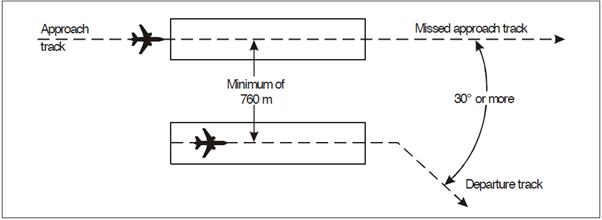
Requirements and procedures for segregated parallel operations
Segregated parallel operations (Figure 4-1) may be conducted on parallel runways:
-
The runway centerlines are spaced by 760 meters
-
The nominal departure track diverges by at least 30 degrees from the missed approach track of the parallel approach.
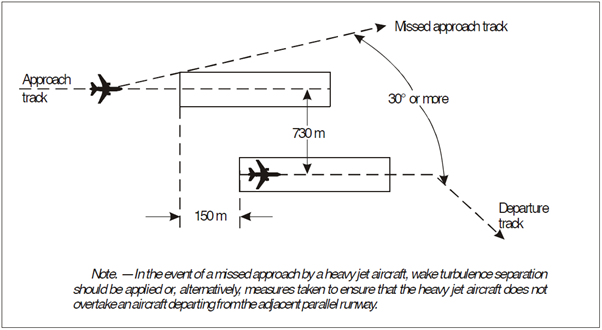
The minimum distance between parallel runway center lines for segregated parallel operations may be decreased by 30 meters for each 150 meters the arrival runway is staggered toward the arriving aircraft, to a minimum of 300 meters (Figure 4-2).
The following types of approaches may be conducted in segregated parallel operations provided suitable surveillance radar and suitable ground services are available such as an ILS.
Segregated parallel operations:
Segregated parallel operations where runways are staggered:
Radar Separation
Radar separation defines the minimum horizontal and vertical distance that must be maintained between two aircraft in flight.
Since safety is the top priority in aviation, controllers must ensure separation is maintained at all times. Radar separation is considered maintained when either horizontal or vertical separation (or both) exist between aircraft.
When aircraft lose both horizontal and vertical separation, it is classified as a Loss of Separation (LoS). If a controller is responsible for a LoS, it will result in an automatic failure during an exam.
Radar separation applies wherever air traffic control (ATC) has radar equipment available. In Approach and Center sectors, radar is always used to verify separation. Tower controllers at international airports also use radar screens, so radar separation must be ensured in the tower environment for departures and approaches.
A separate guide is available detailing radar separation procedures for tower controllers.
When is Separation Required?
The requirement for radar separation depends on the airspace and the applicable flight rules.
Radar Separation Requirements
Radar separation is mandatory between:
-
All flights in airspace A and B (not applicable in some countries).
-
IFR to IFR in airspace C, D, and E.
-
IFR to VFR in airspace C.
-
Special VFR to IFR within a Control Zone (CTR).
Vertical Separation
The following minimum vertical separation applies between aircraft requiring separation:
| Flight Level Range | Vertical Separation | Remarks |
|---|---|---|
| FL410 - UNL | 2000 FT | |
| FL290 - FL410 |
2000 FT | CVSM (Conventional Vertical Separation Minimum, exception) |
| 1000 FT | RVSM (Reduced Vertical Separation Minimum, standard) | |
| GND - FL245 | 1000 FT |
Vertical separation applies at both altitudes (AMSL) and flight levels (FLs).
Vertical separation is not used on final approach, where only horizontal separation is applied.
Horizontal Separation
The following minimum horizontal separation applies between aircraft requiring separation:
| Flight Level Range | Horizontal Separation |
| FL245 - UNL | 5 NM |
| GND - FL245 | 3 NM |
| Final approach (within 10 NM) | 2.5 NM |
Horizontal separation is always measured as a direct line between the centers of aircraft radar targets.
Formation Flight Considerations
-
Formation flights must be separated from other traffic by 1 NM more than the required minimum distance.
-
Two formation flights must be separated from each other by 2 NM more than the required minimum distance.
Wake Turbulence Considerations
If wake turbulence separation requirements exceed the above values, the higher separation value always applies to ensure safety.
Wake Turbulence Separation
Wake turbulence refers to vortex turbulence generated by aircraft, particularly during takeoff and landing. Controllers must ensure minimum separation distances to prevent accidents caused by wake turbulence.
When is Wake Turbulence Separation Required?
Wake turbulence separation applies in situations where wake turbulence is expected, including:
Enroute Separation (Radar-Separated Aircraft)
Separation is required if:
- An aircraft is directly behind another aircraft at the same altitude or less than 1000ft below.
- An aircraft crosses behind another aircraft at its 6 o’clock position, at the same altitude or less than 1000ft below.
Approach and Departure Phases
Separation is required when:
- An aircraft is directly behind another aircraft at the same altitude or less than 1000ft below.
- An aircraft crosses behind another aircraft at its 6 o’clock position, at the same altitude or less than 1000ft below.
- Both aircraft use the same runway or parallel runways less than 760m apart.
- Aircraft use crossing or parallel runways (760m or more apart) and one aircraft flies through the flight path of the preceding aircraft at the same altitude or less than 1000ft below.
Exceptions: When Wake Turbulence Separation is NOT Required
Wake turbulence separation does not apply to:
-
VFR approach flights.
-
IFR approach flights performing a visual approach, where the pilot:
- Has reported the preceding aircraft in sight.
- Has been instructed to follow it and maintain their own separation.
In these cases, a wake turbulence warning must be issued: "CAUTION WAKE TURBULENCE".
Phases of Flight for Wake Turbulence Application
Departure Phase
A VFR flight remains in the departure phase until:
- Reaching 1000ft above aerodrome level.
- Reaching level flight.
- Entering right downwind.
Approach Phase
A VFR flight is in the approach phase when:
- It is at or below 1000ft above aerodrome level.
- It has entered the traffic pattern.
- It has begun its final descent within a control zone.
Special Cases:
A touch-and-go is considered an approaching aircraft until touchdown, after which it is handled as a departing aircraft. A low approach is considered approaching until it crosses the runway threshold, after which it is considered departing.
Wake Turbulence Categories (WTC)
Aircraft are categorized based on Maximum Takeoff Mass (MTOM):
| WTC | MTOM |
|---|---|
| Light (L) | ≤ 7t |
| Medium (M) | 7t < MTOM < 136t |
| Heavy (H) | ≥ 136t |
| Super (J) | A388; A225 |
Aircraft in the Super (J) category are treated as Heavy (H) above FL100. WTC information is always available in the flight plan.
Minimum Wake Turbulence Separation Values
Wake turbulence separation can be distance-based or time-based.
- Distance-based separation is the default standard.
- Time-based separation applies when distance-based separation is not feasible.
Distance-Based Wake Turbulence Separation
| Preceding Aircraft | Following Aircraft | Minimum Separation |
|---|---|---|
| Super |
Heavy | 5.0 NM |
| Medium | 7.0 NM | |
| Light | 8.0 NM | |
| Heavy |
Heavy | 4.0 NM |
| Medium | 5.0 NM | |
| Light | 6.0 NM | |
| Medium | Light | 5.0 NM |
Time-Based Wake Turbulence Separation
Time-based separation is used for departing and approaching aircraft.
If an aircraft departs from an intersection or crossing runway, 1 minute is added to the separation value.
Departing aircraft
| Preceeding | Suceeding | Separation value | Separation value (intersection) |
| M | L | 2 min | 3 min |
| H |
L | 2 min | 3 min |
| M | 2 min | 3 min | |
| J |
L | 3 min | 4 min |
| M | 3 min | 4 min | |
| H | 2 min | 3 min |
Approaching aircraft
| Preceeding |
Suceeding | Separation value |
| M | L | 3min |
| H |
L | 3min |
| M | 2min | |
| J |
L | 4min |
| M | 3min | |
| H | 2min |
Minimum Time Separation: Mixed Arrival/Departure Use with Displaced Threshold
| Suceeding Aircraft | Preceding Aircraft | Time Separation |
|---|---|---|
| Departing Heavy | Super arrival | 2 minutes |
| Departing Light/Medium | Heavy arrival | 2 minutes |
| Departing Light | Medium arrival | 2 minutes |
| Heavy arrival | Super departure | 2 minutes |
| Light/Medium arrival | Heavy departure | 2 minutes |
| Light arrival | Medium departure | 2 minutes |
| Departing Light/Medium | Super arrival | 3 minutes |
| Light/Medium arrival | Super departure | 3 minutes |
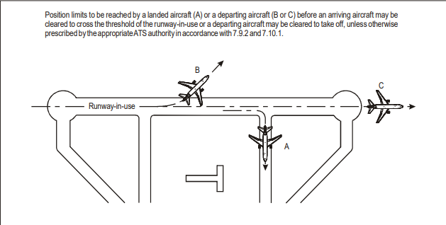
Runway Separation
Only one aircraft may occupy a runway at a time. Takeoff or landing clearance must not be issued if another aircraft is occupying the runway unless specific conditions allow otherwise.
A departing aircraft will not normally be cleared for takeoff until:
- The preceding departing aircraft has crossed the end of the runway-in-use or has started a turn.
- All preceding landing aircraft are clear of the runway-in-use.
- Takeoff clearance may be issued when there is reasonable assurance that prescribed separation will exist at the time of departure.
- If an ATC clearance is required before takeoff, it must be transmitted and acknowledged before issuing the takeoff clearance.
- The takeoff clearance must be issued when the aircraft is ready for departure and at or approaching the departure runway. The runway designator must be included to avoid misinterpretation.
- An immediate takeoff clearance may be issued before the aircraft enters the runway, requiring the aircraft to taxi onto the runway and depart in one continuous movement.
A landing aircraft will not normally be permitted to cross the runway threshold unless:
- The preceding departing aircraft has crossed the end of the runway-in-use or started a turn.
- All preceding landing aircraft are clear of the runway-in-use.
To expedite traffic, a landing aircraft may be instructed to:
- Hold short of an intersecting runway after landing.
- Land beyond the touchdown zone. (Not applicable to HEAVY aircraft.)
- Vacate the runway at a specified exit taxiway.
- Expedite vacating the runway.
Controllers must consider aircraft type, runway length, exit locations, braking action reports, and weather conditions when issuing such instructions. If a pilot is unable to comply, they must inform ATC immediately.
When necessary, such as in low visibility, an aircraft may be instructed to report when it has vacated the runway. The report must be made after the entire aircraft is beyond the relevant runway-holding position.
Reduced runway separation
Reduced Runway Separation (RRS) can only be applied if the following conditions are met:
- Tailwind component does not exceed 5 knots
- Visibility is at least 5 km and the ceiling is 1,000 ft (300 m) or higher
- Wake turbulence separation is maintained at all times
- Braking action is not significantly impaired by precipitation
- On VATSIM, braking is considered impaired by snow (SN), snow grains (SG), ice grains (PL), hail (GR), and rime (GS)
- Rain (RA) and drizzle (DZ) do not affect RRS
- The following aircraft in the RRS sequence must receive traffic information about the preceding aircraft
RRS can only be applied during daylight hours, from 30 minutes after sunrise to 30 minutes before sunset.
Aircraft Categories
For RRS, aircraft are divided into three categories based on size and type:
| Category | Aircraft Type | Examples |
|---|---|---|
| Category 1 | Single-engine propeller aircraft, max takeoff weight ≤ 2,000 kg | C152, C172, P28A, A210, DA40, DR40, DV20, SR22 |
| Category 2 | Single-engine propeller aircraft (2,000 – 7,000 kg) and twin-engine propeller aircraft (≤ 7,000 kg) | DA62, PA34, TBM9, BE58, B350 |
| Category 3 | All other aircraft | AT75, DH8D, C25C, CRJ9, B738, A359 |
Departure Behind Departure
The following departure must receive traffic information about the leading departure. If all conditions are met, the second departure may be cleared for takeoff as soon as the first departure has taken off and is a defined distance ahead.
| Preceding Aircraft | Succeeding Aircraft | Minimum Distance After Takeoff |
|---|---|---|
| Category 1 or 2 | Category 1 | 600 m |
| Category 1 or 2 | Category 2 | 1,500 m |
| Category 3 | Any Aircraft | 2,400 m |
Example:
A DV20 (Cat 1) IFR departs first, followed by a BE58 (Cat 2) VFR. Normally, the second aircraft would have to wait until the DV20 passes the end of the runway. Under RRS, the BE58 can be cleared for takeoff as soon as the DV20 is airborne and at least 1,500 m ahead. This improves runway efficiency.
Arrival Behind Arrival
The second approach must receive traffic information about the first approach. If all conditions are met, the second approach may be cleared for landing before the preceding aircraft has vacated, provided the first aircraft keeps moving and does not backtrack.
| Preceding Aircraft | Succeeding Aircraft | Minimum Distance After Landing |
|---|---|---|
| Category 1 or 2 | Category 1 | 600 m and moving toward an exit without backtracking |
| Category 1 or 2 | Category 2 | 1,500 m and moving toward an exit without backtracking |
| Category 3 | Any Aircraft | 2,400 m and moving toward an exit without backtracking |
Example:
A C172 (Cat 1) IFR lands first, followed by a TBM9 (Cat 2) IFR. Normally, the TBM9 would have to wait until the C172 clears the runway. Under RRS, the TBM9 can be cleared to land as soon as the C172 has passed 1,500 m beyond the threshold and is still moving toward an exit.
Arrival Behind Departure
The arriving aircraft receives traffic information about the departure. If all conditions are met, the landing clearance may be issued once the departing aircraft is airborne and past the defined distance.
| Preceding Departure | Succeeding Arrival | Minimum Distance Past Threshold |
|---|---|---|
| Category 1 or 2 | Category 1 | 600 m |
| Category 1 or 2 | Category 2 | 1,500 m |
| Category 3 | Any Aircraft | 2,400 m |
Example:
A DA40 (Cat 1) departs, followed by a B350 (Cat 2) arriving. Normally, the B350 would wait until the DA40 passes the end of the runway. Under RRS, the B350 can receive landing clearance as soon as the DA40 is airborne and at least 1,500 m past the threshold.
Departure Behind Arrival
RRS does not apply in this case. A departure must wait until a landing aircraft has completely vacated the runway.
| Scenario | Minimum Requirement for the Second Aircraft |
|---|---|
| Departure behind departure | First aircraft is airborne and has passed 600m (Cat 1), 1,500m (Cat 2), or 2,400m (Cat 3) ahead |
| Arrival behind arrival | First aircraft has landed and is still moving toward an exit, at least 600m (Cat 1), 1,500m (Cat 2), or 2,400m (Cat 3) past the threshold |
| Arrival behind departure | Departing aircraft is airborne and has passed 600m (Cat 1), 1,500m (Cat 2), or 2,400m (Cat 3) past the threshold |
| Departure behind arrival | RRS not applicable – standard separation required |
Intersecting runways
Many airports use intersecting runways to accommodate varying wind conditions or maximize efficiency in limited space. Proper separation procedures must be followed to ensure safe operations.
Departure Following a Departure
When two aircraft are departing from intersecting runways, the second aircraft may only begin its takeoff roll if one of the following conditions is met:
- The first aircraft has taken off and initiated a turn that ensures safe separation, or
- The first aircraft has completely crossed the intersection.
Departure Following an Arrival
If a landing aircraft is on the intersecting runway, the departing aircraft may only begin its takeoff roll when:
- The landing aircraft has fully vacated the runway, or
- The landing aircraft has stopped before the intersection as instructed and completed its landing roll, or
- The landing aircraft has crossed the intersection.
Arrival Following a Departure
If an arriving aircraft is following a departing aircraft on an intersecting runway, the arriving aircraft may only cross the runway threshold when:
- The departing aircraft has taken off and initiated a turn that maintains separation, or
- The departing aircraft has completely crossed the intersection.
Arrival Following an Arrival
For two landing aircraft on intersecting runways, the second aircraft may only cross the runway threshold if:
- The first aircraft has vacated the runway, or
- The first aircraft has stopped before the intersection as instructed and completed its landing roll, or
- The first aircraft has crossed the intersection.
Simultaneous landings on intersecting runways are only permitted under the following conditions:
- One of the intersecting runways must have at least 2200 meters of available distance between the threshold and the intersection.
- Additional conditions must be met:
- Visual Meteorological Conditions (VMC) must exist.
- Braking action must not be negatively affected.
- Both aircraft must be informed of the simultaneous landings.
- The aircraft landing on the 2200m runway must stop before the intersection as instructed.
| Scenario | Condition for Second Aircraft to Proceed |
|---|---|
| Departure following a departure | First aircraft has either crossed the intersection or initiated a turn. |
| Departure following an arrival | Landing aircraft has vacated the runway, stopped before the intersection, or crossed the intersection. |
| Arrival following a departure | Departing aircraft has crossed the intersection or initiated a turn. |
| Arrival following an arrival | First arriving aircraft has vacated the runway, stopped before the intersection, or crossed the intersection. |
Opposite direction
When an aircraft departs in the opposite direction, the following aircraft may only commence takeoff when:
- The preceding aircraft has crossed the point where the following aircraft will start its takeoff roll.
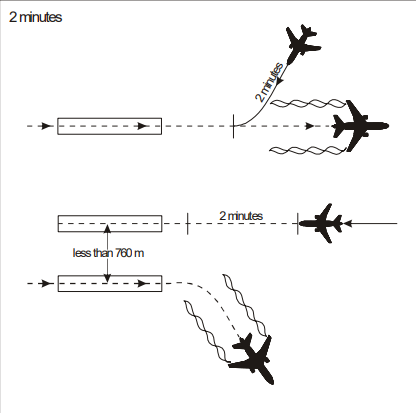
Additionally, a minimum separation of 2 minutes must be applied when:
- A LIGHT or MEDIUM aircraft follows a HEAVY aircraft.
- A LIGHT aircraft follows a MEDIUM aircraft that is making a low or missed approach.
These rules apply to:
- Takeoffs from opposite-direction runways.
- Landings on the same runway in the opposite direction or on a parallel opposite-direction runway separated by less than 760m (2,500 ft).
Two-minute wake turbulence separation for opposite-direction take-off:
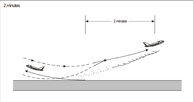
Two-minute wake turbulence separation for opposite-direction landing:
Visual Separation
Visual separation refers to two types of separation procedures used in different scenarios:
-
Visual separation in the vicinity of aerodromes – Relevant primarily for tower controllers and, in some cases, approach controllers.
-
Delegation of separation to pilots during climb or descent – Relevant for approach controllers.
Visual Separation in the Vicinity of Aerodromes
Radar separation (excluding wake turbulence separation and runway separation) may be reduced near an aerodrome if one of the following conditions is met:
-
The tower controller has continuous visual contact with both aircraft and provides traffic information to at least one of them.
-
Both pilots have the other aircraft in sight and confirm they can maintain adequate separation.
-
If one aircraft is following another, the following pilot reports they have the leading aircraft in sight and can maintain separation.
The terms “vicinity of the aerodrome” and “adequate separation” are not explicitly defined, so controllers must use discretion, such as when avoiding a missed approach where minimum separation could be compromised.
Delegation of Separation During Climb or Descent
Under specific conditions, responsibility for separation between two aircraft may be delegated to the pilots.
- Own separation is applied:
- upon crew request;
- in airspace classes D and E only;
- at or below 10,000 ft;
- during climb or descent;
- All flights must be in VMC (they may fly under IFR though);
- All pilots must agree to the use of own separation;
- Alternative instructions should be given to IFR flights if it is considered that VMC may not be maintained for the whole duration of the clearance.
Phraseology Example: Own Separation - Final
| Station | Phraseology |
|---|---|
| ATC | "RAM123, traffic, traffic two o’clock, five miles, A320, report in sight." |
| Pilot | "Traffic in sight, RAM123." |
| ATC | "RAM123, number three, cleared visual approach runway 35R, in the event of missed approach, climb runway heading to 4'000ft, maintain visual separation from A320 to runway 35L." |
Own separation is NOT to be used:
- On controller's initiative;
- In airspace classes A, B and C;
- At night;
- In IMC;
- Above 10,000 ft;
- If all aircraft are maintaining their level;
- If the use of own separation is not agreed by all pilots concerned.
Procedural Control
General
The general principles of air traffic control are the same regardless of whether procedural or surveillance methods are used (i.e. the controller monitors the traffic situations, detects and solves conflicts by providing separation, and ensures orderly flow of the air traffic). The difference lies in the way situational awareness is built and updated (by pilot reports, estimates and visual observation), the separation minima themselves (as described in ICAO Doc 4444, Chapter 5) and the support tools (flight strips instead of a situation display).
Where procedural control is employed, separation is ensured by dividing the airspace either vertically or laterally. In a Control Zone where reliable surveillance is not available, it may be classified as procedural, meaning separation is maintained using specified time or distance criteria. There are four types of procedural separation: lateral, longitudinal, vertical, and visual.
Typical Applications
Typical applications of procedural control include:
- In airspace where surveillance cover is not available (e.g. oceanic airspace or sparsely populated areas)
- In terminal movement areas (TMAs) if the traffic levels are such that they do not warrant the installation and maintenance of a surveillance system
- In aerodrome control zones (CTRs), especially if the traffic density is relatively low and the aerodrome layout is not complex (e.g. only one runway, one apron and a few taxiways)
- Backup solution in case of complete failure of all surveillance-based systems
Separation
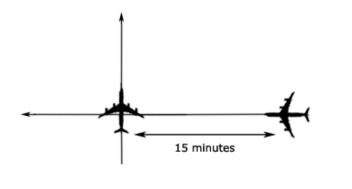
Longitudinal Separation
Longitudinal separation is only applied between aircraft flying on identical or reciprocal tracks.
To maintain longitudinal time separation, pilot-provided estimates must be used to ensure that the time interval between two aircraft meets or exceeds the required minimum.
Time
Same Track:
Aircraft following the same track, including situations where one is climbing or descending through another’s level, must maintain a separation of at least 10 minutes.
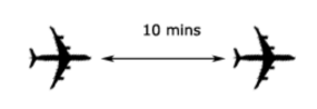
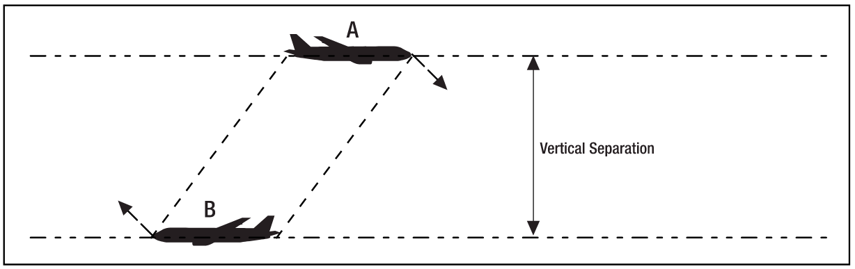
Reciprocal Track:
Aircraft on reciprocal tracks must be separated using vertical separation. A vertical separation minimum of 10 minutes must be in place before the estimated passing time.
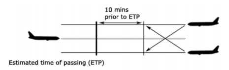
After the estimated time of passing, no aircraft may climb or descend through the other’s level until at least 10 minutes have passed. If positive identification of passing is confirmed, this requirement may be reduced, which will be discussed later in this section.
Distance
Distance Reports:
The lead aircraft must be navigating directly to or from the designated navigational aid. The distance report from the lead aircraft must always be obtained before requesting it from the following aircraft.
Distance checks must be performed as outlined in the table below:
| Condition | Minimum Interval for Distance Checks |
|---|---|
| No speed control applied | 15 minutes |
| Speed control applied to limit closure to ≤ 35 knots or Mach 0.06 | 15 minutes |
| Closure rate exceeds 35 knots or Mach 0.06 | Standard is not valid |
| Speed control applied to maintain a stable or increasing separation | 30 minutes |
Methods of Ensuring Distance-based Separation:
| Method | Conditions | |
|---|---|---|
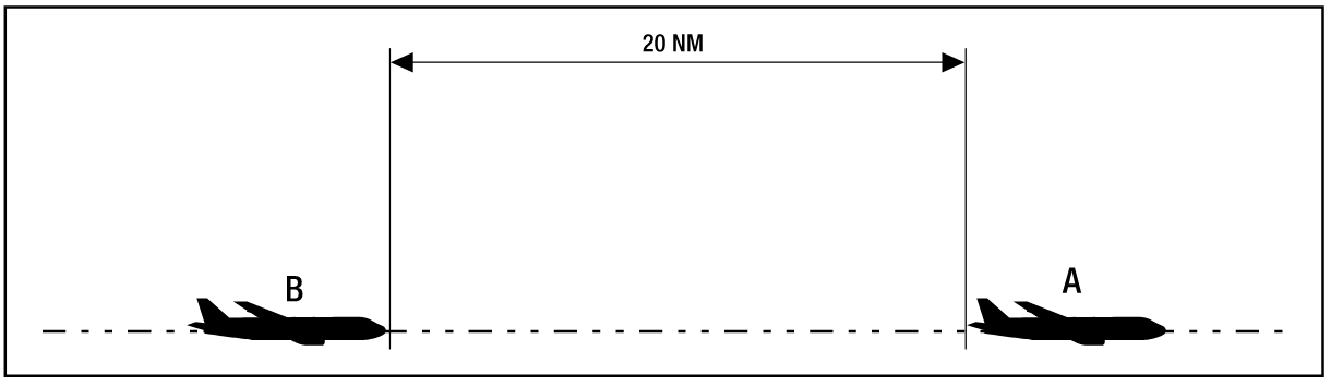
| 20nm Exists Between |
|
|
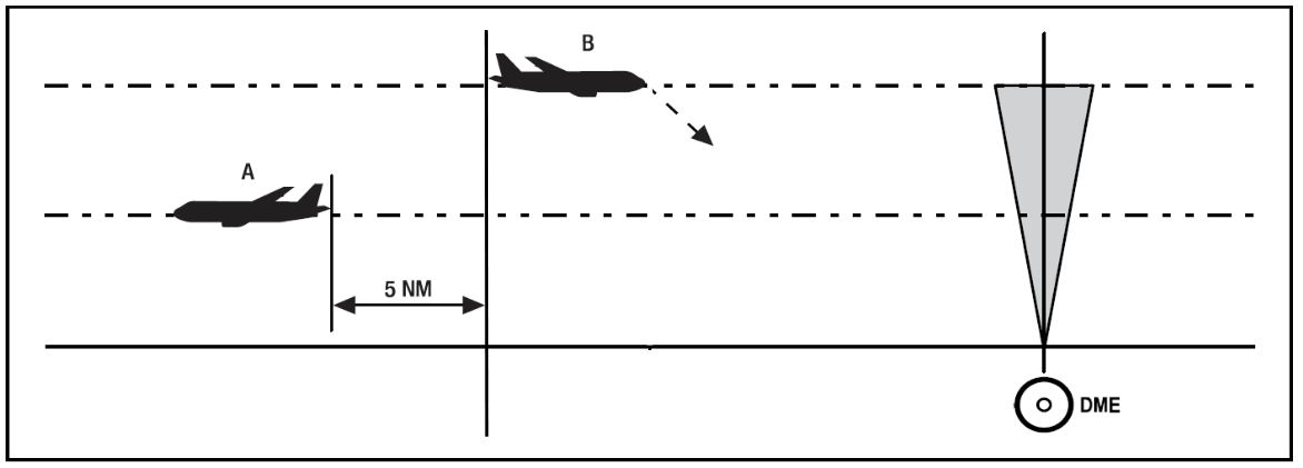
| 5nm Definite Passing |
|
|
| Sight and Pass |
|
|
| Opposite Side of Visual Fix |
|
|
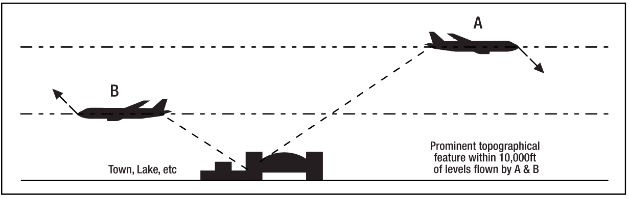
Lateral Separation
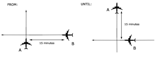
Time-based Crossing Track
Aircraft on crossing tracks, including cases where one is climbing or descending through another’s level, must maintain a separation of 15 minutes at the intersection point.
If a 15-minute separation cannot be ensured at the crossing point, vertical separation must be applied. This vertical separation remains in effect from the time the second aircraft is 15 minutes from the intersection until the first aircraft has passed it by 15 minutes.
Lat Sep Table
Lateral separation is determined based on the concept of a Lateral Separation Point (Lat Sep point)—the distance at which procedural lateral separation is considered to exist, depending on the angle of intersection between two tracks. The required separation distances are outlined in the table below:
| Intersection Angle | Required Separation |
|---|---|
| 0° - 15° | No lateral separation |
| 16° - 44° | 11nm |
| 45° - 135° | 8nm |
| 136° - 180° | No lateral separation |
Visually, an aircraft at point ABC is considered laterally separated from aircraft in the green zones, whereas it is not laterally separated from aircraft in the red zones. These criteria only apply when both aircraft are tracking directly to or from the crossing point.
This method is particularly useful for planning restrictions when surveillance coverage is not guaranteed.
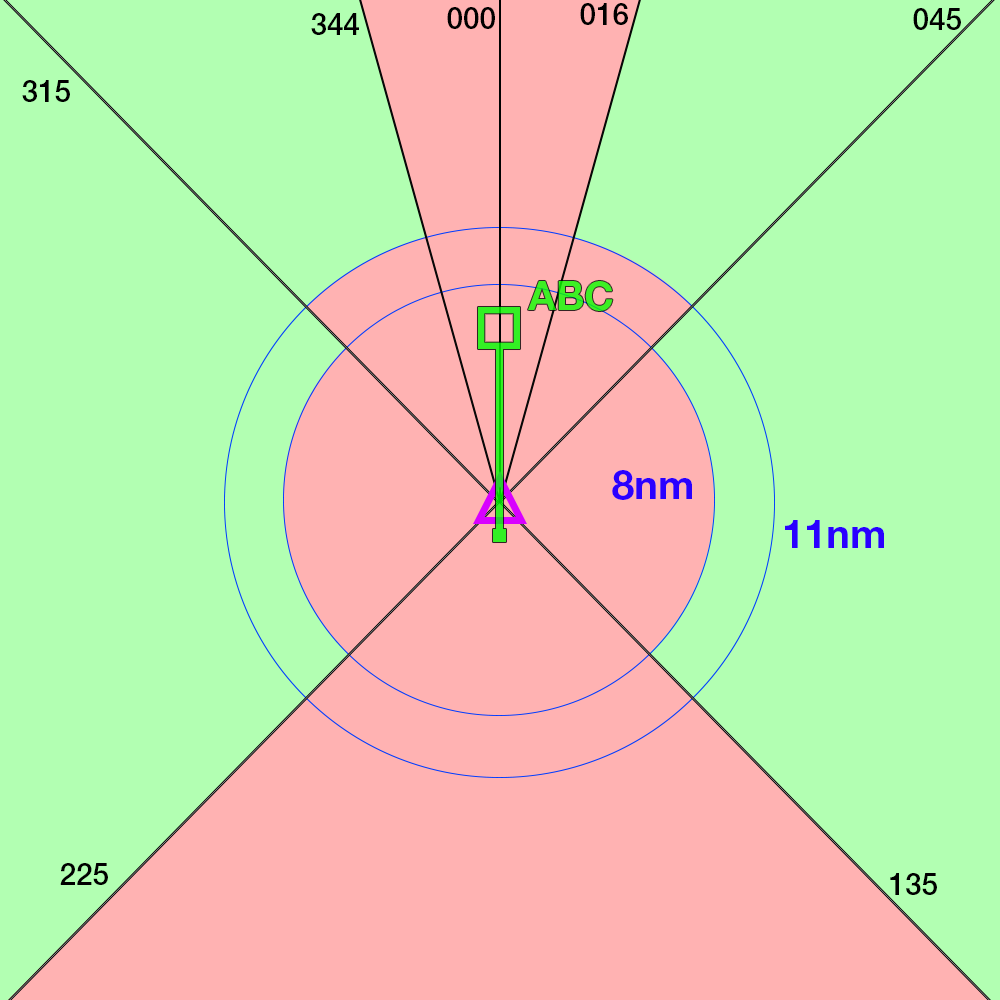
Vertical Separation
Vertical separation is the most commonly used method in non-radar environments, allowing controllers to maintain aircraft at different flight levels without the risk of loss of separation—unless one aircraft needs to climb or descend.
The primary reference for aircraft altitudes and assigned levels is pilot-reported data.
| Altitude / Flight Level | Separation Standard |
|---|---|
| SFC - FL290 | 1000ft |
| FL290 - FL410 | RVSM: 1000ft, Non-RVSM: 2000ft |
| FL410 - FL600 | 2000ft |
| Any Supersonic Aircraft, regardless of FL | 3000ft |
RVSM airspace is only applicable between FL290 and FL410.
An aircraft cannot be cleared to climb or descend into a level that was previously occupied by another aircraft until that aircraft has confirmed it is clear of the relevant levels.
Procedures
Timed Approaches
Timed approaches, utilizing either nonradar procedures or radar vectors to align aircraft with the final approach course, may be conducted at airports with an active tower or approach controller, provided the following conditions are met:
-
The procedure relies on appropriate NAVAIDs and either standard or special instrument approach procedures, or sufficient radar coverage to facilitate:
- Aircraft holding at a designated fix on the approach course or receiving radar vectors for a straight-in approach while adhering to specified minima, including wake turbulence requirements.
- Aircraft proceeding toward the airport along the approach course while crossing the holding or approach fix at an assigned altitude, if required.
- Aircraft continuing descent to execute an approach at the destination airport.
-
Continuous communication must be maintained with the aircraft until the pilot is instructed to switch to the tower frequency.
-
If multiple missed approach procedures exist, none should require a course reversal.
-
If only one missed approach procedure is available, the following conditions must be met:
- A course reversal is not necessary.
- The reported ceiling and visibility meet or exceed the highest prescribed circling minimums for the approach in use.
Ceiling minima are determined by comparing the Minimum Descent Altitude (MSL) with the reported ceiling (AGL) plus the airport elevation.
Approach Sequence
Once an aircraft passes the final approach fix inbound (for a nonprecision approach) or the outer marker or equivalent fix inbound (for a precision approach), clearances for subsequent timed approaches should be issued as follows:
- Clear the following aircraft for approach, instructing it to descend to the altitude vacated by the preceding aircraft.
- Assign a specified time for the following aircraft to cross the final approach fix or outer marker inbound.
- When using radar to manage sequencing, vector aircraft to cross the final approach fix or outer marker at the assigned time.
If an alternative missed approach procedure is unavailable and weather conditions are below the required minima, the next aircraft should only be cleared for approach once the preceding aircraft has landed or canceled its IFR flight plan.
All aircraft must be transferred to the tower frequency before reaching the final approach fix.
Sequence Interruption
If necessary, the established approach sequence may be interrupted to accommodate aircraft executing a different type of approach.
Level Flight Restriction
When weather conditions indicate that an aircraft will be in IFR conditions at the final approach fix (for nonprecision approaches) or the outer marker or equivalent fix (for precision approaches), the second aircraft must be cleared for approach early enough to ensure at least one minute of level flight before crossing the final approach fix or outer marker.
Additional spacing should be applied when needed, considering:
- The relative speeds of the aircraft involved.
- Current weather conditions.
- The distance between the approach fix and the airport.
- The type of approach being conducted.
Time Check
Prior to issuing a specific time for an aircraft to depart the approach fix inbound, a time check should be provided—unless the aircraft is being vectored to the final approach course.
Missed Approaches
- If weather conditions suggest a missed approach is likely, an alternative missed approach procedure should be assigned to the next aircraft.
- If an aircraft executes a missed approach, the next aircraft may continue the approach only if it has been assigned an alternative missed approach procedure.
- Radar control must be maintained, or remaining aircraft must be held at their assigned altitudes until conditions permit issuing further approach clearances.
In cases where a timed approach sequence is in place and an aircraft misses an approach:
- Retain radar control of subsequent aircraft or instruct them to maintain their last assigned altitude (at or above the minimum holding altitude).
- The aircraft should return to the holding or approach fix and remain there until approach clearance can be issued under safe traffic conditions.
Control Practices
Horizontal Speed Control
General
Speed control is one of the most desirable ways to achieve or maintain a desired separation between aircraft. In general, it results in the smallest increase in controller workload and is particularly useful when sequencing aircraft (such as towards a TMA entry point).
The primary variable affecting the future position, and consequently, separation between aircraft is ground speed. However, it is generally impractical to instruct aircraft to maintain a certain ground speed. Therefore, speed assignments are made with reference to indicated airspeed (IAS) or Mach number.
Use of horizontal speed control
Speeds may be used to:
- Adjust separation (different speeds applied between aircraft)
- Maintain separation (the same speed applied between aircraft)
- Absorb delay by reducing speed enroute (as an alternative to holding)
- Avoid or reduce vectoring:
- As an alternative to vectoring
- In combination with vectoring to reduce the number and magnitude of heading changes required
Considerations
Applying speed control
Most jet turbine aircraft will be unable to quickly increase or decrease speed, especially at higher altitude, so due consideration must be given to the time taken for an aircraft to reach a desired speed. In certain cases, the speed control may need to be applied, one or two miles prior to when the desired spacing is achieved.
Due consideration must also be given to prevailing winds aloft, as a headwind will decrease an aircraft’s ground speed and a tailwind will increase an aircraft’s ground speed. This may affect the magnitude of the speed instruction that is given to an aircraft.
Aircraft performance characteristics
Speeds in excess of the maximum or minimum speeds shall not be assigned to aircraft. Due consideration must be given to the performance characteristics of different aircraft. This ensures that aircraft do not operate too close to high speed/low-speed buffet regions of the flight envelope, especially for aircraft at higher levels (FL350 and above). (See Table 7-1)
| Aircraft category | Safe operating Mach | Maximum IAS (below FL250) |
|---|---|---|
| SUPER (A380) | 0.82 – 0.87 | 330 |
| HEAVY (B747, B787, A350) | 0.82 – 0.87 | 330 |
| HEAVY (B777, B767, A330, MD11) | 0.81 – 0.85 | 320 |
| MEDIUM (A320, B737) | 0.75 – 0.79 | 300 |
Speed control during climb or descent
Instructions for aircraft to maintain a high rate of descent and a low speed, or a high rate of climb and high speed, are generally incompatible.
When aircraft are instructed to increase speed during a climb or decrease speed during a descent, they can be expected to maintain a short period of level or near-level flight in order to comply with the speed instruction. Conversely, when aircraft are instructed to reduce speed during a climb or increase speed during a descent, they can be expected to increase their rate of climb or descent, respectively.
Effectiveness
Speed control generally takes more time to achieve the desired separation as compared to other techniques such as vectoring, so due consideration must also be given to the volume of airspace available to achieve the desired separation.
The longer the controller waits before applying speed control, the more drastic the speed change needs to be in order to achieve the desired separation at the handover point. Should this be the case, the controller should revert to vectoring to achieve separation.
Relationship between Mach number and true airspeed
When aircraft are flown with reference to Mach number, the true airspeed of an aircraft will decrease with increasing altitude. This must be considered when applying Mach number control between aircraft at different flight levels, as aircraft at higher levels will be flying slower than those at lower levels despite reporting the same Mach number.
Relationship between indicated airspeed and true airspeed
When aircraft are being flown with reference to indicated airspeed, their true airspeed will increase with increasing altitude. Therefore, aircraft at higher altitude will be flying faster than those at lower altitude, despite reporting the same indicated airspeed.
Mach/airspeed crossover
Aircraft climbing under speed control should be given a Mach number to maintain during the crossover point between indicated airspeed and Mach number to ensure that they maintain a safe operating margin and do not unexpectedly increase speed during the climb.
Conversely, descending aircraft should be given an indicated airspeed to maintain during the crossover, so their speed does not continue to increase as the aircraft descends.
Rules of thumb
- 0.01 Mach = 6 knots
- Speed difference of 6 knots gives 1 NM of separation change every 10 minutes
- Speed difference of 30 knots gives 1 NM of separation change every 2 minutes
- Speed difference of 60 knots gives 1 NM of separation change every minute
- True airspeed (TAS) = Indicated airspeed (IAS) + 6 knots per 1000 ft above MSL
Vectoring
General
Vectoring is achieved by instructing aircraft to maintain a heading that will result in it following a desired ground track. It is one of the most effective techniques to establish and maintain horizontal separation between traffic and is far more effective than speed control in doing so, producing the desired result much more quickly. However, it results in a larger increase in controller as compared to other methods.
When aircraft are placed on a vector, they must be informed of the reason for the vector, and the expected point where they are expected to re-join the flight planned route.
The procedures laid down in 5.2 shall apply when aircraft are under radar vectors.
Use of vectoring
Navigation assistance
This may also be used to provide navigational assistance to VFR aircraft should they become lost.
Circumnavigating airspace
If aircraft is approaching special use airspace such as danger, restricted and prohibited areas and a climb or descent is unfeasible, aircraft may be vectored around the airspace.
Conflict prevention
In situations where there is adequate separation between aircraft projected to cross each other at the same level, but it is only slightly above separation minima, aircraft may be instructed to “MAINTAIN PRESENT HEADING”.
This technique of “locking” the heading ensures that the minimum separation will be maintained between aircraft, and the aircraft will not make any turns such as to follow an airway or terminal procedure.
Conflict solving
If a level change is not possible, or practical, aircraft may be issued a heading change in order to ensure horizontal separation minima is maintained. In most cases, only a relatively small change in heading is required to achieve the desired result. This results in a minimal change to the aircraft’s total flight distance and therefore to its fuel consumption.
After the conflict has been solved and separation is assured aircraft may be instructed to resume their own navigation.
Sequencing
Aircraft may be sequenced to a sector boundary point using a combination of speeds and vectors. The objective of sequencing is to establish and maintain a minimum separation between the leading and following aircraft.
Vectoring geometry
Conflict geometry
Crossing point
The crossing point is the point where the projected flight paths between two aircraft are expected to cross. It is fairly easy to determine the crossing point as it is only dependent on the projected tracks of two aircraft and is unaffected by speed and wind.
Closest point of approach (CPA)
The minimum distance between two aircraft at the time they pass each other is known as the closest point of approach (CPA). In general, the separation between two aircraft continues to reduce after the first aircraft crosses the track of the second aircraft until reaching the CPA.
CPA is dependent on the angle of the trajectories of the two aircraft and their projected ground speed and therefore the time taken to reach the crossing point. For this reason, it is more complex to calculate than crossing point as it requires the use of trigonometry.
Closest point of approach is displayed on the radar screen along the projected path of an aircraft and is color coded yellow. A red color code indicates that the CPA is below the required separation minima. It should be noted, however that this is an instantaneous prediction and may not necessarily be accurate if aircraft vertical and horizontal speed change and should therefore be used with caution.
Determining CPA
- A crossing angle of 90 degrees means separation will be reduced by 30% between crossing point and CPA. As a result, a separation of 7.2 NM at the crossing point is required to ensure 5 NM separation at CPA.
- A crossing angle of 60 degrees means separation will be reduced by 20% between crossing point and CPA. As a result, a separation of 6.3 NM at the crossing point is required to ensure 5 NM separation at the CPA.
- A crossing angle of 60 degrees means separation will be reduced by 10% between crossing point and CPA. As a result, a separation of 5.6 NM is required at the crossing point to ensure 5 NM separation at the CPA.
- A crossing angle of 120 degrees means separation will be reduced by 50% between the crossing point and the CPA. As a result, a separation of 10 NM is required at the crossing point to ensure 5 NM separation at the CPA.
- A crossing angle of 150 degrees means separation will be reduced by 75% between the crossing point and CPA. As a result, a separation of 20 NM is required at the crossing point to ensure 5 NM separation at the CPA.
Selecting the aircraft
Vectoring both aircraft
This is the most commonly used method to solve conflicts on reciprocal tracks. Although it increases controller workload, as multiple transmissions need to be made to different aircraft, it has less of an impact on each aircraft’s trajectory resulting in a minimal increase in distance flown. For this technique to work, both aircraft need to alter course in the same direction (e.g., both turn mright).
Vectoring the aircraft behind
This method is used when two aircraft are maintaining altitude and one is overtaking the other. The aircraft further from the crossing point is given a vector to increase separation. This is much more effective than vectoring the aircraft closer to the crossing point.
Vectoring the aircraft requesting a level change
If accommodating a climb or descent request would cause and aircraft to pass through the level of another and subsequently result in insufficient separation between them, the aircraft requesting the level change is usually the one that is given the vector.
This is usually done in three steps, first a vector is given to establish lateral separation between the two aircraft, followed by a vector to parallel the track, while at the same time accommodating the climb request. Once the aircraft has passed through the level of the other with sufficient vertical separation, a direct routing is given to the requesting aircraft to re-establish it on the planned track.
More complex situations
In more complex situations where the aforementioned techniques would not necessarily, generally controllers should follow the principle of requiring minimal intervention to achieve the desired result.
Turn direction
Aircraft on reciprocal tracks
Aircraft on opposing tracks should be vectored in the direction that would increase separation
Aircraft on crossing tracks
The aircraft further away from the crossing point should be “aimed” at the current position of the aircraft closer to the crossing point. This results in the distance from the crossing point of the leading aircraft to be reduced significantly, where the distance from the crossing point of the second aircraft is only marginally reduced. This method causes the second aircraft to pass behind the first.
For example, if the aircraft further from the crossing point has traffic on the left-hand side, it should be turned to the left to “aim” it towards the crossing traffic. Although it may seem counter-intuitive, this method will increase the separation between the aircraft.
Aircraft on the same track requesting a level change
The requesting aircraft should be turned into the wind, which will result in a reduction in its ground speed, resulting in a larger rate of increase of separation and placing the aircraft being vectored further behind. A sufficiently strong wind can be much more effective than speed control in managing an aircraft’s speed.
Consideration of the planned track
When aircraft are being vectored, due consideration must also be given to the planned flight paths of the aircraft such that the vector does not result in a significant increase in the track miles flown by the aircraft. In this case, aircraft may be issued a direct routing to “cut the corner”, which will have the same effect as a vector in that direction.
Airspace consideration
The dimensions of the airspace must also be considered when issuing vectors to aircraft. Aircraft shall not be vectored closer than 2.5 NM to the boundary of the airspace that a controller is responsible for, as this may require other actions such as coordination and further conflict solving.
Crossing angle
After the direction of turn is selected, the extent of the heading change must be determined. The crossing angle is crucial as it determines:
- The increase of separation after vectoring
- The separation reduction between the crossing point and the CPA The general impact of the crossing angle is as follows:
- Right angle (crossing) tracks allows the 1-in-60 rule to be used
- Acute angle (similar) tracks lead to:
- Less separation gained be vectoring as opposed to other options. This scenario may sometimes require a heading change of 20 degrees or more, and if wind conditions are unfavorable, it may require an even greater turn.
- In combination with vectoring to reduce the number and magnitude of heading changes required
- Obtuse angle (reciprocal) tracks lead to:
- Greater separation reduction after the crossing point
- More separation gained by vectoring. A small turn of 5 to 10 degrees is often enough to achieve the desired separation.
Associated risks
Forgetting that an aircraft has been issued a vector
This has a negative impact on flight efficiency and may also “surprise” the next controller if the airway or arrival procedure makes a sharp turn at the transfer point and the aircraft does not.
To mitigate this risk, the aircraft tag is marked before handoff to the next controller when the aircraft is placed under radar vectors.
Miscalculation of wind impact
If a controller attempts to sequence an aircraft behind another and by turning but instructs the aircraft to turn so the tailwind increases, the maneuver may have no effect as the tailwinds increases the aircraft’s speed effectively reducing the expected benefit from vectoring.
In addition, the wind speed and direction may be different at different levels and may vary significantly. Consequently, the headwind/tailwind/crosswind component will also vary, affecting the desired result. For example, the drift angle may be different at different levels, resulting in aircraft flying on converging tracks despite flying parallel headings.
This may be mitigated by assigning slightly diverging headings to aircraft being vectored.
Miscalculation of aircraft performance
Generally climbing aircraft increase their ground speed and descending aircraft will reduce their ground speed. The speed at cruise level may be up to twice as high as the speed at lower altitudes.
To mitigate this risk, controllers must always have an awareness of the performance characteristics that are altered by changes in altitude.
Rules of thumb
- Turn radius in NM = Ground speed in knots / 100
Level Change
General
During various phases of flight, level changes by aircraft may be necessary for the purpose of separation.
When issuing a level change clearance, vertical and horizontal separation between aircraft shall always be assured. Controllers must ensure that the cleared level will not result in a loss of separation with any other traffic in the vicinity prior to issuing a level clearance.
Due consideration be given to aircraft on crossing or reciprocal tracks, as well as aircraft that are on the same track which may be separated vertically but may not have adequate horizontal separation.
If there is any doubt as to whether separation will be assured an alternative clearance must be provided.
Level change clearance
Climb clearance
During a climb, when an aircraft is expected to cross, or is on the same track as proximate traffic and separation may reduce to below minimum horizontal separation, they shall only be cleared:
- To a level 1000 ft below traffic that is maintaining level flight; or
- To a level vacated by traffic if its mode C readout indicates a climb; or
- To a level 1000 ft below the clearance level of traffic that is descending
Descent clearance
During a descent, when an aircraft is expected to cross, or is on the same track as proximate traffic and separation may reduce to below minimum horizontal separation, they shall only be cleared:
- To a level 1000 ft above traffic that is maintaining level flight; or
- To a level vacated by traffic if its mode C readout indicates a descent; or
- To a level 1000 ft above the clearance level of traffic that is climbing
Horizontal speed control in combination with a level clearance
For two or more aircraft on the same track, the level clearance requirements in 9.2.2, and 9.2.3 may be exempted provided horizontal speed control has been applied and appropriate minimum horizontal separation exists and will continue to exist.
Vertical speed control in combination with a level clearance
For aircraft on crossing tracks, the requirements in 9.2.2 and 9.2.3 may be exempted, provided adequate vertical speed control has been applied and adequate horizontal separation exists and will continue to exist throughout the level change maneuver.
Associated risks
Incorrect altimeter setting
An incorrect altimeter setting between QNH and standard pressure may result in a loss of separation between aircraft at transition level and transition altitude. To mitigate this risk, an additional buffer shall be used between transition altitude and level.
Confusion between altitude and flight level
Often, confusion may occur between the terms “ALTITUDE” and “FLIGHT LEVEL”. In order to mitigate this risk, controllers must be vigilant when listening to a read back of the cleared level when transitioning between altimeter settings and reiterate the clearance and pass the QNH if necessary.
Level busts
Aircraft maintaining a very high rate of climb or descent may overshoot the cleared level in some circumstances. If aircraft are expected to maintain a high rate or climb descent, an additional buffer of vertical separation may be required in order to ensure that a level bust will not result in a loss of mseparation.
Rules of thumb
- Aircraft will lose approximately 300 ft per 1 NM travelled forward during descent
- Aircraft need 10 NM to lose 3000 ft
- Aircraft need 16 NM to lose 5000 ft
- Aircraft need 33 NM to lose 10,000 ft
- A tailwind will increase descent track miles required; a headwind will decrease descent track miles required.
- If a rapid descent is required, aircraft should be instructed to maintain a high airspeed and then reduce speed during level flight.
Vertical Speed Control
General
Vertical speed is a useful method of maintaining separation between aircraft that are climbing or descending. Aircraft may be instructed to maintain a specific climb or descent rate. This is most useful when aircraft are climbing or descending through the level of other aircraft or are descending in a holding pattern.
Application of vertical speed control
Vertical speed control may be applied:
- To accommodate climb requests (by requesting an aircraft to expedite passing a level)
- For separation of arriving and departing traffic in opposite directions
- To descend arriving aircraft below enroute traffic
- For vertical sequencing between climbing or descending aircraft
- For corrective action (when unrestricted vertical speed is insufficient)
Benefits
Efficiency
Effectively used vertical speed control allows for continuous climbs and descents and therefore better efficiency. In addition, it permits descents to start close to top of descent and allows timely accommodation of climb and descent requests.
Reduced controller workload
This method also ensures vertical separation is maintained, resulting in reduced workload because of a reduced need for vectoring and/or horizontal speed control.
Risks
Reduced separation
The margin for error is reduced as this method relies on maintaining minimum vertical separation, which is much lower than minimum horizontal separation, therefore any non-compliance may result in a loss of separation between aircraft.
Non-compliance or misunderstanding
A misunderstanding of the instruction may result in the desired separation not being achieved. A correct readback does not guarantee compliance.
Aircraft may be unable to maintain the assigned rate of climb or descent beyond a certain level. If this occurs, there is a possibility the flight crew may not inform the controller.
Considerations
Aircraft performance
Certain aircraft types such as the Airbus A321 and Airbus A340 are unable to maintain high rates of climb.
In addition, climb rates can be expected to decrease when aircraft are approaching their cruise level, and will therefore generally be unable to maintain rates of climb in excess of 1000 ft/min. High temperatures will further reduce this value.
High rates of descent are generally incompatible with low airspeeds. Instructions to maintain both a high descent rate and low speed should be avoided.
Aircraft autopilots generally take a few seconds to respond. The transition time to achieve a vertical rate should be taken into account when issuing vertical speed control.
Level busts
When aircraft are within 2000 to 3000 ft of their assigned level, they should not be instructed to maintain vertical speeds in excess of 1500 ft/min in order to avoid a level bust and to prevent possible TCAS RA activation.
Safety buffer
In order to mitigate the risk of traffic on reciprocal tracks losing separation a safety buffer of one or two minutes needs to be applied by issuing the clearance earlier or assigning a higher vertical speed to maintain.
Expedited climbs or descents
The phrases “EXPEDITE CLIMB” and “EXPEDITE DESCENT” do not specify vertical speeds and should be used with caution. Climbing aircraft will climb at the maximum rate possible, which may sometimes be insufficient to achieve the desired result. The use of safety margins and alternative clearances should therefore be considered.
Aircraft descending will generally increase their vertical speed to 2000 ft/min or greater when instructed to expedite. For this reason, it is advisable that this instruction is given early on in the descent.
Alternative clearance
Controllers must always have an alternative plan available to accommodate a climb or descent request if aircraft are unable to comply with a vertical speed instruction.
Rules of thumb
- A vertical speed of 2000 ft/min results in a change of 10 flight levels in 5 minutes
- A vertical speed of 2500 ft/min results in a change of 10 flight levels in 4 minutes
- A combined vertical speed of 4000 ft/min (such as when one aircraft is climbing and the other is descending), results in a change of 20 flight levels in 5 minutes
Holding
General
Holding is an instrument procedure employed by ATC as a delay tactic to manage the rate of traffic flow into a terminal area, to ensure that its capacity is not exceeded during peak arrival times, as well as times when traffic flow rate is constrained such as during low visibility or single-runway operations.
Holding is generally managed by area control, and aircraft are instructed to hold at fixes that are\ outside the respective terminal area. In exceptional cases, holding may be conducted within the terminal area at published holding fixes on the respective STAR.
During times of peak arrivals, a dedicated holding stack controller is often used to reduce the workload of the area controller and allow more efficient level allocation and timely hold exits.
Hold capacity
All holding fixes have a maximum holding capacity that is determined by the minimum and maximum holding levels. When the hold’s maximum capacity is reached, i.e., aircraft are entering the hold at levels above the maximum holding level, aircraft shall be instructed to proceed to an alternative holding fix.
Hold management
Hold entry
Aircraft shall generally enter the hold via one of three entry procedures:
- Parallel entry (sector 1)
- Offset/teardrop entry (sector 2)
- Direct entry (sector 3 )
Hold entry sectors:
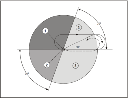
Aircraft that have reported entering the hold may be considered established over the holding fix.
Descent clearance
When aircraft are instructed to descend in the hold, they shall only be cleared:
- To a level 1000 ft above traffic below that is maintaining level flight; or
- To a level vacated by traffic below if its mode C readout indicates a descent
Hold exit
Once aircraft are ready to be sequenced for the arrival, they should be instructed to exit the hold. There are three primary methods of instructing an aircraft to exit the hold, each with their own set of risks and benefits.
Exit on completion of hold
This technique allows aircraft to be given the hold exit instruction in advance when radio traffic permits. However, this does not allow for an expeditious exit from the hold and may sometimes take up to 5 minutes to accomplish the hold instruction. This means that the exit must be planned for in advance, potentially increasing controller workload.
To accomplish this, aircraft must be instructed “ON COMPLETION, EXIT THE HOLD”.
Exit with a direct
For an immediate exit, aircraft may be instructed to proceed directly to the holding fix from their present position. This allows for an exit from the hold requiring a maximum of 2 minutes to accomplish. However, this method is liable to error from a mis-programmed FMC.
In order to mitigate this risk, it is preferable to instruct the aircraft to proceed directly to the first fix on the STAR instead of the holding fix. This guarantees that the aircraft will not remain in the hold, as they will bypass the holding fix.
An additional advantage of this technique is that aircraft remain within the holding protected area under most circumstances.
Vectored exit in combination with a direct
Vectors used in combination with instructions to proceed directly to a fix allow for an expeditious hold exit and has many advantages, as it allows the aircraft to be immediately taken out of the hold and establishes horizontal separation with holding traffic. This allows the holding traffic to be descended to a lower altitude provided that the exiting traffic is kept at minimum radar separation from holding traffic.
To accomplish this, aircraft are issued an appropriate vector to either extend the outbound heading, or to fly a heading that is perpendicular to the holding inbound course towards the non-holding side. A combination of both these headings may be used to exit multiple aircraft simultaneously.
Once aircraft have been vectored clear of holding traffic, they may be given a direct to either the holding fix or to the first fix on the STAR. Consideration shall be given to the risks discussed in 6 .3.3.2.
The minimum holding level is above the highest minimum sector altitude and assures terrain and obstacle clearance. However, as with any other time when vectoring an aircraft, consideration shall be given to the minimum radar maneuvering altitudes, as well as adjacent airspace.
Aerodrome Control
Aerodrome Control Service
General provisions
Aerodrome control towers issue information and clearances to aircraft under their control to achieve a safe, orderly, and expeditious flow of air traffic at and in the vicinity of an aerodrome. The main objective of aerodrome controllers is to prevent collisions between:
- Aircraft flying within the designated area of responsibility of the control tower, including the aerodrome traffic circuit;
- Aircraft operating on the maneuvering area;
- Aircraft landing and taking off;
- Aircraft and vehicles operating on the maneuvering area;
- Aircraft of the maneuvering area obstructions on that area;
Aerodrome controllers should maintain a continuous watch on all flight operations on and in the vicinity of the aerodrome. Watch shall be maintained by visual means which may be augmented by ATS surveillance under low visibility conditions.
The function of an aerodrome controller is normally performed by different positions:
- Aerodrome controller, responsible for operations on the runway and aircraft flying within the area of responsibility of the control tower (control zone);
- Ground controller, responsible for traffic on the maneuvering area with the exception of runways;
- Clearance delivery position, normally responsible for the delivery of IFR clearances and, where necessary the adjustment of start-up times.
Where parallel or near-parallel runways are used for simultaneous operations, individual aerodrome controllers should be responsible for operations on each of the runways.
Control of aerodrome traffic
Designated positions of aircraft in the aerodrome traffic and taxi circuits
The following positions in the aerodrome traffic and taxi circuits are where aircraft receive clearance from the aerodrome control tower (Figure 6-1). Aircraft should be watched closely as they approach these positions so that proper clearances may be issues without delay. Wherever possible, the controller should initiate the radio call without having to be contacted by the pilot.
- Aircraft initiates call to taxi for departing flight. Runway-in-use information and taxi clearances given (runway-in-use may be omitted if the aerodrome has a functional ATIS).
- If there is conflicting traffic, the departing traffic will be held at this position. Engine run-up will, when required, normally be performed here.
- Take-off clearance is issued here, if not practicable at position 2.
- Clearance to land is issued here as practicable.
- Clearance to taxi to apron is issued here.
- Parking information is issued here, if necessary.
Designated positions of aircraft from a control tower viewpoint:
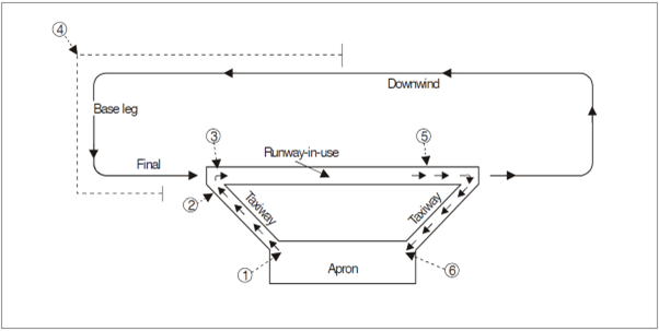
Control of taxiing aircraft
Prior to issuing taxi clearance, controllers should establish where on the aerodrome and aircraft is parked. Taxi clearances should be concise and provide adequate information so that pilots are able to follow the correct taxi route, avoid a collision with other aircraft, and minimize the occurrence of aircraft inadvertently entering an active runway.
When a taxi clearance contains a clearance limit beyond that of an active runway, explicit instruction must be given to aircraft to hold short of or cross that runway.
A taxi route should wherever possible be described by the use of taxiway designators, runway designators. Wherever required, instructions to follow or give way to other taxiing aircraft should be provided.
Aircraft shall not be permitted to line up or hold on the approach end of a runway-in-use whenever another aircraft is landing, until the landing aircraft has passed in front of the aircraft holding short.
Aircraft holding short of a runway:
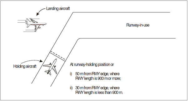
Multiple Line-ups on the Same Runway
Line-up instructions may be issued to more than one aircraft at different points on the same or crossing runways provided that:
- It is during daylight hours;
- All aircraft are continuously visible to the aerodrome controller;
- All aircraft are on the same Radiotelephony (RT) frequency;
- Pilots are advised of the number of aircraft ahead in the departure sequence and the position/runway from which these aircraft will depart;
- The physical characteristics of the runway do not render preceding aircraft in the departure sequence invisible to succeeding aircraft on the same runway.
Example:
ATC: ABC123 LINE UP AND WAIT RUNWAY 22, INTERSECTION BRAVO, NUMBER 2 FOR DEPARTURE, NUMBER ONE IS BLU JET B737 DEPARTING FROM ALPHA ONE.
A/C: LINE UP AND WAIT RUNWAY 22, INTERSECTION BRAVO, NUMBER 2, ABC123
Control of traffic in the aerodrome traffic circuit
Aircraft in the traffic circuit shall be separated in accordance with the minima listed in 6.3 except:
- Aircraft operating in different areas or different runways on aerodromes suitable for simultaneous runway operations.
- Military aircraft
Sufficient separation should be maintained for aircraft operating in the traffic circuit to allow for arriving or departing aircraft.
Aircraft should be cleared to join the traffic circuit in a direction which conforms with other aircraft already in the circuit. In addition, an aircraft may be instructed to join any part of a traffic circuit.
IFR aircraft executing an instrument approach should be allowed to make a straight in approach unless visual maneuvering is required for the completion of the procedure (such as a circling approach).
Order of priority for arriving and departing aircraft
An aircraft in the final stages of an approach to a runway shall be given priority over aircraft intending to depart from the same or intersecting runway.
Runway incursion or obstructed runway
If an aerodrome controller, after a take-off clearance or a landing clearance has been issued becomes aware of a runway incursion, or imminent runway incursion, the following action should be taken:
- Cancel the take-off clearance for a departing aircraft;
- Instruct a landing aircraft to execute a go-around or missed approach;
- In all cases inform the aircraft of the obstruction or incursion and its location in relation to the runway.
Control of departing aircraft
Departure sequence
Departures should normally be cleared for take-off in the order which they are ready, except where deviations may be made in this order of priority to facilitate the maximum number of departures with the least average delay.
Factors which should be taken into consideration are:
- Types of aircraft and their relative performance;
- Routes to be followed take-off
- Any specified minimum departure interval between take-offs;
- Need to apply wake turbulence separation minima;
- Aircraft which should be afforded priority;
- Aircraft subject to ATFM requirements.
Separation minima
Except where wake turbulence separation (6.6), departure track separation (6.7) or reduced minima (6.5) is applied, aircraft will normally only be cleared for take-off:
- Once the preceding aircraft has crossed the end of the runway in use; or
- The preceding departing aircraft has commenced a turn to clear the runway; or
- Until all preceding landing aircraft are clear of the runway in use
Separation between departing and arriving aircraft:
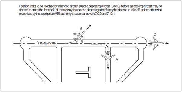
Take-off clearance
Take-off clearance may be issued when there is reasonable assurance that the separation minima in 6.3.2 or 6.5 will exist when the aircraft commences take-off.
The expression “TAKE-OFF” shall only be used when issuing or cancelling a take-off clearance.
Subject to 6.3.1, take-off clearance shall be issued when the aircraft is ready for take-off at or approaching the runway holding point. To minimize confusion, the runway designator should be included in the take-off clearance.
In the interest of expediting traffic, a clearance for immediate take-off may be issued to an aircraft before it enters the runway. The aircraft will be expected to carry out the lineup and take-off in one continuous movement.
Control of arriving aircraft
Separation minima
Except where wake turbulence separation (6.6), departure track separation (6.7) or reduced minima (6.5) is applied, aircraft will only be cleared to cross the landing threshold when:
- The preceding departing aircraft has crossed the end of the runway-in-use or has started a turn; or
- The preceding landing aircraft is clear of the runway-in-use. (See Figure 6-2)
Landing clearance
Landing clearance may be issued when there is reasonable assurance that the separation minima in 6.4.1 and 6.5 will exist when the aircraft crosses the runway threshold, provided that a clearance to land will not be provided until a preceding landing aircraft has crossed the runway threshold. To reduce the potential for misunderstanding, the runway designator shall be included in the landing clearance.
Landing roll-out maneuvers
Where necessary to expedite traffic, a landing aircraft may be instructed to vacate at a specified exit point, or to expedite vacating the runway.
In requesting aircraft to perform specific landing roll-out maneuvers, the type of aircraft, location of exit, runway length, meteorological conditions and reported braking action should be considered by the controller.
When necessary or desirable (such as during low visibility operations) an aircraft may be instructed to report when a runway has been vacated.
Reduced runway separation minima (RRSM)
Subject to a safety assessment for specific aerodromes, lower separation minima than those specified in 6.3 and 6.4 may be used and is termed as reduced runway separation minima (RRSM).
RRSM must not be applied between a departing aircraft that is following a preceding landing aircraft.
RRSM is subject to the following conditions:
- Wake turbulence separation minima shall be applied;
- Visibility shall be at least 5 km and ceiling not less than 300 ft;
- Tailwind component should not exceed 5 kt;
- There shall be available means such as suitable landmarks that allow controllers to assess the separation between aircraft. A surface surveillance system may be utilized to fulfil this requirement;
- Minimum separation continues to exist between two departing aircraft immediately after the take-off of the second aircraft;
- Traffic information shall be provided to the crew of the succeeding aircraft;
- Braking action shall not be adversely affected by contaminants such as slush, ice or snow.
Time-based wake turbulence separation minima (non-radar)
Applicability
Wherever applicable, controllers shall be responsible for the application of the wake turbulence separation minima specified in 5.4.4.
ATC shall not be required to apply wake turbulence separation for the following cases:
- Arriving VFR flights landing on the same runway as a preceding SUPER, HEAVY or MEDIUM aircraft; and
- Between IFR flights executing a visual approach when the aircraft has reported the preceding aircraft in sight and has been instructed to follow and maintain own separation
Where aircraft have been instructed to maintain their own separation and where otherwise deemed necessary, ATC shall provide a caution of possible wake turbulence. It is the pilot’s responsibility in this mcase to maintain a safe following distance from the preceding arrival.
Successive departing aircraft
A minimum separation of 3 minutes shall be provided between a LIGHT or MEDIUM aircraft taking off behind a SUPER aircraft and; 2 minutes shall be applied between a HEAVY taking off behind a SUPER aircraft, and a LIGHT or MEDIUM aircraft taking of behind a HEAVY aircraft when they are using:
- The same runway
- Parallel runways separated by less than 760 meters
- Parallel runways separated by more than 760 meters if the projected flight path of the second aircraft will cross the projected flight path of the first aircraft at the same altitude or up to 1000 ft below.
Two-minute separation for departing aircraft:
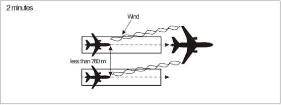
Two-minute separation for crossing aircraft:
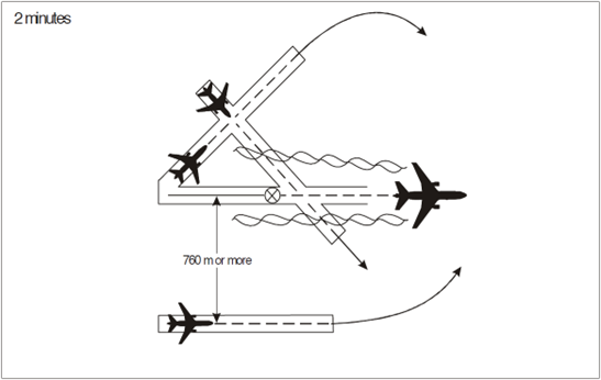
A minimum separation of 4 minutes shall be applied between a LIGHT or MEDIUM aircraft taking off behind a SUPER aircraft and; 3 minutes shall be applied between a LIGHT or MEDIUM aircraft taking off behind a HEAVY aircraft and a LIGHT aircraft taking off behind a MEDIUM aircraft from:
- An intermediate part of the same runway
- An intermediate part of a parallel runway separated by less than 760 meters
Three-minute wake turbulence separation for following aircraft:
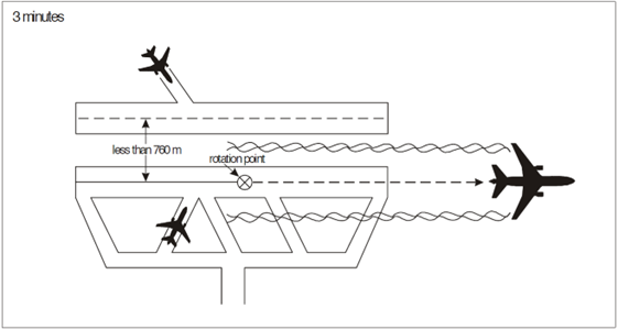
Displaced landing threshold
A minimum separation of 3 minutes shall be applied between a LIGHT or MEDIUM aircraft and a SUPER aircraft and; 2 minutes shall be applied between a LIGHT or MEDIUM aircraft and a HEAVY aircraft and between a LIGHT aircraft and a MEDIUM aircraft when operating on a runway with a displaced landing
threshold when:
- A departing LIGHT or MEDIUM aircraft follows a SUPER aircraft arrival and a departing LIGHTaircraft follows a MEDIUM aircraft arrival; or
- An arriving LIGHT or MEDIUM aircraft follows a HEAVY or SUPER aircraft departure and an arriving LIGHT aircraft follows a MEDIUM aircraft departure if the projected flight paths areexpected to cross.
Separation of successive IFR departures
Departures on diverging tracks
For successive IFR departures, if the departure track of a following aircraft diverges by more than 30 degrees from the leading aircraft, and the controller has confirmed by visual observation, the following aircraft may be cleared for take-off when:
- The leading aircraft has reached a point where appropriate separation will exist from the following aircraft; or
- The leading aircraft has turned to clear the departure track of the following aircraft
If the departure track of a following aircraft differs by more than 20 degrees from the leading aircraft, the following aircraft may be cleared for take-off when:
- Radar identification will be established within 1 NM of the departure end of the runway used for take-off; and
- The leading aircraft is more than 1 NM ahead of the following aircraft and confirmed by visual or radar observation as having turned to clear the departure track of the following aircraft.
Departures on the same track
The separation between two successive IFR departures following the same departure track is 2 minutes, provided the leading aircraft maintains a speed 40 knots or more higher than the trailing aircraft (Figure 6-5).
Separation between successive IFR departures:
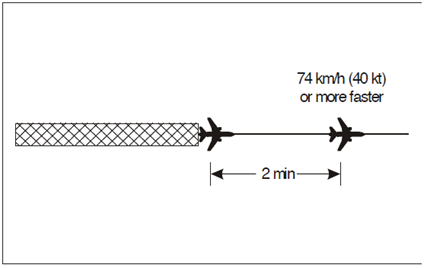
Aerodrome Techniques
Departure separation
General
Departure separation often has a major effect on the handling capacity of an aerodrome. Effective use of departure separation and departure sequence planning maximizes efficiency while still complying with minimum time-based separation requirements.
Applying separation
It is often impractical to try to time the separation based on the rotation of the aircraft, as the controller must know exactly when each aircraft will rotate, and requires them to keep a close eye on the take-off roll of the aircraft which is often impractical, especially during times of high traffic workload.
In order to minimize workload while still maximizing efficiency, the separation must be applied to the start of the take-off roll, as opposed to the rotation point. This is much easier to do and allows the controller to focus elsewhere in between take-off clearances.
For example, if the separation requirement between two aircraft is 2 minutes, the controller must start a 2-minute timer as soon as the preceding aircraft commences the take-off roll and deliver the next aircraft’s take-off clearance such that the second aircraft commences their take-off roll exactly 2 minutes after the first.
The time taken for a pilot to read back the instruction and commence a take-off roll is usually 15 seconds, so the take-off clearance in this example must be delivered 1 minute and 45 seconds after the first aircraft has commenced its take-off roll to ensure efficient use of departure separation.
Departure sequence
General
Effective planning of the departure sequence ensures that the average delay experienced on the aerodrome is minimized, maximizing aircraft throughput. If done correctly, this ensures that in most instances the separation required between successive take-offs is minimized.
Planning the departure sequence
In general, ensuring that aircraft on the same departure are always paired with an aircraft on a departure in a different direction will minimize average delay. Where there are different weight categories of aircraft, aircraft should in general be paired with an aircraft of the same category.
Approach Control
Terminal Area (TMA) Techniques
Procedure design
RNAV arrivals
Aircraft are positioned on a 4 to 5-mile downwind on opposing sides of the runway, allowing aircraft to perform continuous descents, and resulting in consistent behavior when vectoring aircraft for sequencing base-to-final.
The STARs also incorporate level and speed restrictions, which assure separation from departing traffic, as well as terrain and obstacles. Although, traffic permitting, the speed restrictions may be cancelled. Level restrictions may also be cancelled in compliance with the specific procedures for the terminal area.
RNAV departures
Allowing aircraft to follow the published reduces controller workload, but consideration must be given to the interaction between departure and arrival procedures, and appropriate climb instructions must be given.
Where airports are equipped for simultaneous instrument departures, allowing aircraft to follow the published procedure will assure separation between parallel departing aircraft.
Initial arrival sequencing
Sequencing before aircraft reach downwind
In some cases, aircraft may require vectors before reaching the downwind leg of the STAR. In these cases, an appropriate vector should be issued to the aircraft to achieve the target separation as appropriate.
In addition to vectors, aircraft may be issued direct routings from the upwind leg of the trombone to the downwind leg of the trombone, allowing more optimal sequencing of aircraft and reduced controller workload.
Rules of thumb
Controllers shall keep the following in mind when providing vectors to final. For aircraft travelling at the same speed:
- “Aiming” an aircraft well ahead of the preceding aircraft will reduce separation rapidly
- “Aiming” an aircraft at the preceding aircraft will cause the separation to increase slowly
- “Aiming” an aircraft behind the preceding aircraft will cause the separation to increase rapidly.
Base to final sequencing
Use of standard vectors
When vectoring aircraft base to final, standard headings shall always be used. This permits consistent behavior of aircraft when turning base and intercepting the final approach course, which allows the timing of the vectors to be adjusted to account for factors such as winds with a high degree of accuracy.
In general, the following standard vectors shall be used when sequencing aircraft from base to final:
- A 90-degree base vector, perpendicular to the runway course
- A 30-degree intercept vector to intercept the final approach course
Speed, turn radius and turn rate
Turn radius and turn rate of an aircraft are proportional to their airspeed and bank angle. As the bank angle and/or airspeed increases, the turn rate and turn radius of an aircraft will increase.
As most modern jet turbine aircraft autopilots are programmed to utilize a constant 25-degree bank angle, as the airspeed of an aircraft reduces, its turn rate and turn radius will increase. Controllers must have a sound understanding of this relationship, as it is particularly important during base to final sequencing.
Timing of the base turn
Assuming aircraft are travelling at the same speed, the timing of the base turn depends primarily on the distance of the downwind from the final approach course.
If an aircraft initiates a base turn abeam traffic on final, the final separation between the aircraft will be approximately one mile greater than the initial distance between the two aircraft at the time of the base turn.
For example, if the downwind leg is 4 miles from the final approach course, the separation when the following aircraft establishes will be approximately 5 miles from the leading aircraft, assuming the following aircraft initiates the base turn as the two aircraft pass abeam each other.
Allowance must also be made for the reaction time of the pilot, and autopilot response time. This generally requires the base turn to be anticipated by approximately one mile.
Using this technique, the timing of the base turn may be adjusted to account for differing wake turbulence-based radar separation requirements. Turning the aircraft earlier or later will result in a corresponding reduction or increase in separation on the final approach course, respectively.
Compression on final approach
In order to minimize the risk of a loss of separation on the final approach, a safety margin must be added to the required minimum spacing to account for a phenomenon known as “compression”.
Compression is a result of a combination of factors but is primarily due to the fact that aircraft final approach speeds are generally significantly lower (approximately 130 to 150 knots) than the speed control that is applied to the aircraft until 4 miles. In addition, variation in winds between higher and lower levels, may result in unexpected variations in aircraft ground speed, possibly causing a trailing aircraft to have a higher than anticipated closure rate towards the preceding aircraft.
In general, a buffer of approximately 1 to 1.5 miles is sufficient to account for compression. Often, this buffer may be completely eroded by the time the leading aircraft crosses the landing threshold, but its application assures that no loss of separation will occur.
However, controllers must be careful not to apply buffers that are too large, as this results in a reduction in arrival rate and, as a result, a reduction in the overall capacity of the terminal area and increases the arrival delay required during peak arrival times.
Departure sequencing
Airspeed profile
During the initial climb out, most jet turbine aircraft follow approximately the same airspeed profile. The initial climb speed immediately after take-off is typically dictated by speed restrictions on the SID, after which aircraft will accelerate to a speed of 250 knots.
Passing 10,000 ft, aircraft will accelerate to a cruise-climb speed (typically 270 to 320 knots) until approximately 30,000 ft, after which they transition to their planned cruise Mach number.
Speed control
Controllers must be aware of the expected acceleration points on the SID where the airspeed will rapidly increase. This may occasionally be undesirable and require assignment of a lower speed to maintain separation.
Conversely, aircraft may be instructed to accelerate early if separation with the leading aircraft is adequate. This allows for increased capacity of the departure procedure and minimizes the need to vector traffic off the SID to increase separation.
Vectors
In some instances, vectors may be required in order to increase separation before aircraft transition to the enroute phase. When vectoring is applied, the aircraft shall always be turned away from the leading aircraft’s planned track.
The heading changes to achieve the desired separation should not exceed 30 degrees off track, as this technique results in a very rapid increase in the separation, and time must be allowed for the aircraft to carry out the heading necessary heading change maneuver.