Provision of Air Traffic Service
- Tower Controller
- The Approach Controller
- The Area Controller
- Runway Change Guide
- Emergencies
- Identification
Tower Controller
Start-up
A start-up clearance is permission from ATC for an aircraft to start its engines, confirming that the airport can accommodate the resulting noise. This clearance indicates that the controller has assessed the surrounding airspace, verified the flight plan, and deemed it safe for the aircraft to begin its departure process. Pilots must request start-up clearance from ATC before starting their engines.
DEL also issues the start-up clearance with the phrase "start-up approved," which permits engine start. However, the pilot must still coordinate the actual starting of the engines with the ground crew. Engine start is not permitted while on stand but may occur after pushback or when the ground crew has deemed it safe on a remote stand. Start-up clearance is only issued if the flight can expect pushback soon.
During heavy traffic scenarios, DEL manages departure capacities by withholding start-up clearances when necessary. This prevents airport capacity from being exceeded by too many aircraft maneuvering on the surfaces of the airport. Effective coordination between all aerodrome controllers is critical for managing departures efficiently.
In many cases, the aircraft will also require pushback to taxi to the departure runway. Start-up and pushback clearances are often issued together, especially when no delays are anticipated. Controllers should ensure that pilots have received the latest ATIS broadcast and the current local QNH before departure. Providing the QNH with the start-up or pushback clearance is often a good practice.
Pushback
After or during start-up clearance, aircraft parked in positions requiring pushback are typically moved onto a taxiway by a tug. Smaller aircraft may use a procedure called "power back," enabling them to push back and taxi out under their own power without the need for a tug.
ATC must specify the pushback procedure, including the direction (e.g., "facing south"). Aircraft handed over from the Ground Controller (GND) should be ready for pushback, having reached their Target Off-Block Time (TOBT). If no obstructions are present, pushback clearance is issued immediately.
| Station | Phraseology |
| Pilot | Marrakech Tower, TVF67MM, stand 7, request pushback. |
| ATC | TVF67MM, Marrakech Tower, pushback approved, face west runway 10. |
| Pilot | Pushback approved, face west runway 10, TVF67MM. |
The pushback direction depends on the aircraft’s location, runway configuration, and apron traffic flow. Pushbacks temporarily block taxiways, so controllers must proactively manage traffic, especially at large airports. If a pushback cannot occur immediately (e.g., due to another aircraft or an inbound taxiing), the pilot should be informed with a “hold position” instruction and, if possible, given a brief explanation of the delay.
In cases where multiple aircraft are ready for pushback, controllers may deviate from the "first come, first served" rule to optimize overall traffic flow. Conditional pushback instructions can also be issued during high traffic volumes, such as when an aircraft must wait for another to pass behind it before pushing back. This approach improves taxiway coordination and efficiency.
Conditional pushback transfers some responsibility to pilots and is particularly helpful when managing multiple aircraft pushing back in close proximity. However, controllers must ensure that all instructions are clear and unambiguous to avoid misunderstandings. Simpler instructions are preferable if there is any uncertainty about pilot comprehension.
Advanced procedures, such as "push and pull," can be used to manage complex scenarios, such as clearing a taxiway quickly or coordinating pushbacks for adjacent aircraft. Controllers should only use advanced techniques if they are comfortable and confident in their ability to manage the situation effectively.
| Station | Phraseology |
| Pilot | Mohammed V ground, RAM800F, stand C8, request pushback. |
| ATC | RAM800F, Mohammed V ground, short pushback approved face south to finish abeam stand C6, runway 35R. |
| Pilot | Short pushback approved face south to finish abeam stand C6, runway 35R, RAM800F. |
Clearance delivery
The aerodrome controller is responsible for issuing an en-route clearance to a departing IFR aircraft before departure. Typically, pilots request en-route clearance prior to start-up.
Standard clearances for departing aircraft must include the following elements:
a) Aircraft callsign
b) Clearance limit, usually the destination aerodrome
c) Designator of the assigned Standard Instrument Departure (SID), if applicable
d) Initial level, unless specified in the SID description
e) Assigned SSR code
f) Additional instructions or information not included in the SID, such as frequency changes
| Station | Phraseology |
| Pilot | Tunis ground, TUX1758, AT72 stand P26, information F, requesting en-route clearance to Palermo. |
| ATC | TUX1758, Tunis ground, cleared to Palermo, CBN3A departure, climb initially altitude 4000ft, squawk 4661. |
| Pilot | Cleared to Palermo, CBN3A departure, climb initially altitude 4000ft, squawk 4661, TUX1758. |
| ATC | TUX1758, correct. |
Taxi
Taxi clearances must include clear and concise instructions to safely guide pilots to the holding point of the departure runway. If a taxi clearance involves crossing a runway, it must explicitly include either a clearance to cross or an instruction to hold short of the runway.
Pilots may be cleared to taxi even if another aircraft ahead of them is not yet ready to taxi. In such cases, the pilot must stop behind the preceding aircraft and only proceed once it moves. For complex taxi routes, dividing the clearance into smaller sections simplifies the pilot's readback and reduces errors, ensuring active ATC monitoring throughout.
Hold short and give-way instructions must be issued to resolve potential ground conflicts, depending on the traffic situation. However, if two aircraft are not in immediate conflict (e.g., sufficient separation at crossing taxiways), explicit instructions may not be necessary but require close monitoring with intervention if needed.
To maintain efficient ground movement and minimize frequency congestion, controllers should use give-way instructions and conditional clearances. Intersection departures can improve sequencing efficiency for Tower controllers. If a pilot is taxiing to a runway intersection, they should be asked if they are able to accept the intersection departure.
Pilots should be handed over to the next position (e.g., TWR) once:
- They are cleared to the handover point (e.g., runway holding point).
- They are free of conflicts (e.g., no unresolved intersections with other aircraft).
- No further instructions are required from the current controller.
Unnecessary stops due to delays in handovers should be avoided. Controllers should regularly scan the airport to identify aircraft ready for handoff.
For unfamiliar pilots or expedited movement, it is helpful to specify directions (e.g., "Turn left onto taxiway Bravo").
Backtrack Procedure:
Backtracking involves an aircraft entering a runway from an intersection, taxiing in the opposite direction of the runway, and proceeding to the runway's beginning. At the end, the aircraft turns around to utilize the full runway length for takeoff. This procedure is often used when no designated taxiway leads to the runway's beginning or when the taxiway is unsuitable for certain aircraft types.
Line-up
A line-up clearance must be issued to departing aircraft before giving a take-off clearance. Line-up clearances can also be issued as conditional clearances, allowing aircraft to line up behind other traffic when appropriate. Efficient use of the frequency is critical, as only one instruction can be given at a time. Controllers must prioritize transmissions to maintain efficiency and reduce delays.
Aircraft must not be permitted to line up and hold on the approach end of a runway-in-use while another aircraft is landing, until the landing aircraft has passed the holding point. Conditional line-up clearances delegate responsibility to the pilot by instructing them to line up behind specific traffic. For this, good visibility is essential, and the pilot must be advised of the traffic involved. If visibility is poor or the intersection angle is too acute (less than 90 degrees), the pilot must first confirm that they can see the relevant traffic.
Conditional clearances can improve frequency efficiency by filling gaps but often take longer to issue than standard line-up clearances. For example, if a landing aircraft is already near the runway threshold or another aircraft has started its take-off run, a standard line-up clearance is usually more appropriate. Multiple simultaneous conditional clearances are only feasible if the restricting aircraft is directly involved in the sequence (e.g., the next aircraft taxiing past the restricted one).
Departures are typically cleared in the order they are ready, but adjustments may be made to optimize efficiency and minimize delays. Factors influencing the sequence include:
- Aircraft type and performance (e.g., jets vs. turboprops)
- Wake turbulence separation requirements (e.g., departing a medium aircraft before a heavy to avoid delays)
- Routes after takeoff (e.g., aircraft on the same SID requiring separation)
- Priority flights (e.g., medical, SAR, or state flights)
Controllers must aim to maintain minimum separation between aircraft to avoid unnecessarily large gaps, as even small delays can significantly reduce departure capacity. Using intersection departures and conditional line-up clearances can further optimize sequencing and frequency usage.
Take-off clearance
Take-off clearance may be issued when there is reasonable assurance that required separation will exist when the aircraft begins its takeoff. Typically, a departing aircraft will not be cleared for takeoff until the preceding aircraft has either crossed the runway end, started a turn, or until all landing traffic is clear of the runway.
Tower controllers are responsible for ensuring that separation is maintained after departure. At aerodromes with procedural approach control, additional separation requirements may apply. The term "takeoff" should only be used in radiotelephony when clearing an aircraft for takeoff or when canceling a take-off clearance.
In certain situations, take-off or landing clearances can be issued even if the runway is not yet clear. However, there must be a high degree of confidence that the runway will be clear when the clearance takes effect. This procedure can reduce frequency load and improve efficiency, especially in high-traffic situations, but requires significant experience and situational awareness.
Reasonable assurance means being confident that the runway will be clear at the appropriate time. For example, if a departure is scheduled to take off before a landing aircraft, the controller can predict whether the runway will be clear when the inbound aircraft reaches the runway threshold. In such cases, a landing clearance may be issued before the departing aircraft has left the runway, provided all separation requirements will be met.
This procedure can also be applied under reduced runway separation. Wake turbulence or radar separation requirements must still be adhered to. While traffic information is not mandatory in these scenarios, providing it can enhance situational awareness for both pilots and controllers.
Landing clearance
An aircraft on final approach or in the process of landing normally has priority over an aircraft intending to depart from the same or an intersecting runway. Landing aircraft will not be permitted to cross the runway threshold until preceding departing aircraft have either crossed the runway end, started a turn, or until all previous landing aircraft are clear of the runway.
The approach controller is responsible for maintaining wake turbulence separation for arriving aircraft. However, wake turbulence separation is not required for VFR traffic; in such cases, ATC should issue a warning (e.g., "Caution wake turbulence").
Landing and Roll-Out Maneuvers:
To expedite traffic, landing aircraft may be instructed to:
- Land beyond the touchdown zone ("long landing").
- Vacate the runway at a specific exit taxiway.
- Expedite vacating the runway.
When issuing roll-out instructions, controllers must consider factors such as aircraft type, runway length, exit locations, reported braking action, and weather conditions. Heavy aircraft should not be instructed to land beyond the touchdown zone.
In certain situations, such as low visibility, pilots may be asked to report when the runway has been vacated. Tower controllers typically receive approaching aircraft from the approach controller at 8–12 NM before the runway. Controllers should issue landing clearance as early as possible. If no conflicting departures exist, clearance should be given immediately upon initial contact.
A pilot must receive landing clearance before crossing the runway threshold (if advised to expect late clearance) or before reaching minimums during an instrument approach. Failure to receive clearance in time will result in the pilot initiating a go-around. The approach controller is responsible for separation until the aircraft crosses the runway threshold. If two approaches are at risk of losing separation, the tower controller must instruct one aircraft (usually the trailing one) to go around before separation is lost. Traffic information may also be provided to improve situational awareness.
Missed approaches
A missed approach must be instructed if separation (wake turbulence or radar) from preceding traffic cannot be ensured, and all other measures (e.g., speed reductions, delegating visual separation) have been exhausted or are impractical.
Reasons for Missed Approaches:
-
Pilot-Initiated:
- Unstable approach.
- Missed touchdown zone.
- TCAS Resolution Advisory (RA).
- Wind shear or thunderstorms on final approach.
- Landing clearance not received.
- Technical issues (e.g., landing gear problems).
-
Controller-Initiated:
- Runway not clear (e.g., preceding aircraft still on the runway).
- Anticipated loss of separation (e.g., simultaneous approaches too close).
Missed approaches are a standard procedure, not an emergency, and all tower controllers must be prepared to handle them calmly and professionally.
Steps to Handle Missed Approaches:
-
Instruct Missed Approach:
Use clear and audible instructions, e.g., "RAM123, go around," repeating if necessary. Briefly explain the reason (e.g., "traffic on runway" or "separation not ensured"). -
Acknowledge Pilot-Initiated Missed Approaches:
Respond with "RAM123, roger." There is no need to instruct the standard missed approach procedure, as this is part of the approach clearance. Avoid sending additional radio messages unless necessary for separation. -
Establish Separation and Provide Traffic Information:
If the missed approach conflicts with other aircraft, provide traffic information and take steps to establish separation:- Radar Vectors: Issue headings to avoid conflicting tracks.
- Altitude Restrictions: Maintain separation by limiting climb/descent to specific altitudes (at least above MVA).
- Visual Reference: In good weather, a pilot can be instructed to maintain visual reference below MVA with a disclaimer (e.g., "Maintain visual reference until passing [MVA]").
-
Coordinate with Approach or Other Stations:
Every missed approach must be coordinated with the approach controller, especially at airports without delegated IFR separation to the tower. If applicable, provide verbal coordination for clarity. -
Inquire About the Reason:
If the missed approach reason is unclear, request the pilot to report it (e.g., "RAM123, report reason for missed approach"). Relevant information, such as wind shear or technical issues, should be passed to following traffic and the approach controller. -
Handoff to Approach:
Once the aircraft is clear of conflicts and the immediate situation is resolved, transfer it back to the approach controller. Ensure the reason for the missed approach is communicated to prevent redundant queries.
The Approach Controller
Sequencing
While the Tower (TWR) controller primarily focuses on departures, the Approach (APP) controller is responsible for managing arrivals, ensuring they are sequenced safely and efficiently. This involves preventing arrivals from being too close together (which could force a go-around due to an occupied runway) or too far apart (which could result in unnecessary airborne holding and increased fuel consumption).
Sequencing can be managed using several key concepts:
- Separation: The minimum vertical or lateral distance required between two aircraft. This includes radar separation and wake turbulence separation, both of which are critical in approach operations.
- Spacing: The desired distance between aircraft on final approach, which depends on factors such as weather conditions, airport layout, traffic volume, and pilot proficiency.
- Compression: A phenomenon that occurs when a leading aircraft reduces speed on final approach while trailing aircraft continue at a higher speed, causing them to close the gap. Controllers must anticipate this effect and adjust spacing accordingly.
For example, if the required spacing on final approach is 7 NM, an additional 1 NM can be added to account for compression, aiming for 8 NM final spacing when no additional wake turbulence separation is required.
The APP controller must consider several factors when determining final approach spacing:
- Airport Layout: The number of runways, their configurations, and operational capabilities.
- Runway Exit Design: High-speed exits allow aircraft to vacate the runway more quickly, reducing spacing requirements.
- Traffic Volume: Depending on demand, priority may be given to either arrivals or departures, requiring close coordination with TWR.
- Low Visibility Procedures (LVPs): Increased spacing is necessary during reduced visibility conditions.
- Ground Situational Awareness: Monitoring ground movements to adjust spacing for optimal traffic flow.
To establish and maintain proper spacing, controllers should first:
- Reduce the speed of trailing aircraft or
- Increase the speed of leading aircraft, then adjust the speeds of other aircraft accordingly.
Aircraft may be assigned specific speed instructions, such as:
-
Maximum speed
-
Minimum clean speed (minimum speed without flaps, speed brakes, or landing gear deployed)
-
Minimum approach speed
-
A specified IAS (Indicated Airspeed)
-
Controllers should avoid instructing aircraft to reduce speed while maintaining a high descent rate, as these maneuvers are often incompatible.
-
Aircraft should be allowed to remain in a clean configuration for as long as possible.
-
Above FL150, turbojet aircraft should not be reduced to less than 220 knots IAS, which is close to their minimum clean speed.
-
On intermediate and final approach, only minor speed adjustments (not exceeding ±20 knots IAS) should be used.
The following speed recommendations ensure efficient sequencing and predictable spacing:
| Distance from Runway | Maximum IAS |
|---|---|
| 15 NM | 250 knots |
| 12 NM | 220 knots |
| 10 NM (Glideslope Intercept) | 200 knots |
| 7 NM | 190 knots |
| 6 NM | 180 knots |
| 5 NM | 170 knots |
| 4 NM | 160 knots |
- Pilots should not exceed 200 knots upon reaching the glideslope (approximately 10 NM out).
- The approach clearance does not cancel speed restrictions, unless explicitly stated by the controller.
- If unsure whether a pilot is aware of the speed restrictions, it is best to reissue them rather than assume the pilot will adjust preemptively.
- Assigning 180 knots to 6 NM can lead to less precise approaches, as different aircraft types decelerate at different rates. Using 160 knots to 4 NM or 170 knots to 5 NM provides more consistency, reducing spacing deviations to around 0.3–0.4 NM.
- When workload increases, reduce aircraft speeds earlier to maintain control over sequencing.
- Avoid shortening aircraft paths too much, as this can disrupt the flow and spacing.
- Use standard speeds consistently to maintain an organized sequence.
- Prioritize situational awareness and proactive adjustments to prevent unnecessary go-arounds.
ATC issues climb and descent clearances to facilitate departures, arrivals, or to help aircraft avoid adverse weather conditions. As a rule of thumb, controllers can estimate that an aircraft descends at approximately 300 feet per NM (or 1,000 feet per 3 NM), commonly referred to as the 3:1 rule.
For example, when guiding an aircraft over the downwind leg, it should not be higher than 8,000 feet abeam the field; otherwise, it will be too high to turn onto a 10 NM final. To compensate for excessive altitude, pilots may adjust their descent rate at their discretion. However, controllers may assign a specific descent rate if necessary—but should act promptly, as even with speed brakes, an aircraft’s descent rate has its limits.
ATC can also manage vertical speed during both climb and descent to ensure separation between successive or crossing aircraft. This is particularly useful in high-traffic scenarios. In TopSky radar, the assigned rate of climb/descent (ARC function) is marked in the aircraft’s radar label.
When issuing an approach clearance, pilots are expected to descend to the published altitude for the approach. If the controller requires a different altitude, this must be explicitly stated.
Vectoring
Radar vectoring is the process of guiding an aircraft using ATC-assigned headings instead of standard IFR procedures (SID/STAR/Instrument Approach). Controllers must adhere to the Minimum Vectoring Altitude (MVA), which ensures obstacle clearance while vectoring aircraft.
When issuing radar vectors, controllers must:
- Inform the pilot of the purpose of the vector and specify the limit of the vector (e.g., "Vectoring for ILS approach Runway 36").
- When terminating vectoring, instruct the pilot to resume own navigation.
- Aircraft must not be vectored closer than half of the separation minimum (i.e. closer than 2.5 NM if the separation minimum is 5 NM) from the limit of the airspace which the controller is responsible for, unless otherwise specified in local arrangements.
- Avoid vectoring aircraft into uncontrolled airspace, except in emergencies or to circumvent severe weather.
- If an aircraft reports unreliable directional instruments, instruct the pilot to make all turns at an agreed rate and to comply with instructions immediately upon receipt.
When vectoring an IFR flight or issuing a direct routing that takes an aircraft off an ATS route, controllers must ensure that prescribed obstacle clearance is maintained at all times until the pilot resumes navigation. If necessary, the minimum vectoring altitude (MVA) must be adjusted for low-temperature corrections.
Radar vectors can be provided in two ways:
- Heading Assignment: e.g., "Turn left heading 180°."
- Relative Turn Instruction: e.g., "Turn right by 10°."
- This should only be used when there is insufficient time to request a specific heading.
If a radar vector is not self-explanatory (e.g., for final approach), the reason should always be provided (e.g., "Turn left heading 180° for spacing").
Important Considerations:
- When an aircraft is already in a turn, avoid ambiguous instructions like "Turn left/right by..." since the aircraft may not know which heading this refers to. Instead, use "Stop turn" if an immediate heading correction is needed.
- For ILS or localizer approaches, vectoring should be within 30° of the final approach course.
- Example: Runway 36 → Heading 330° or 030° for intercept.
RNAV Arrivals and Point Merge System
The Point Merge System is a specific RNAV-based arrival structure that consists of:
- A merging point
- An arc that arriving aircraft follow until further instruction
Controllers issue a "direct to" clearance to the merging point when appropriate. Since the distance from any point along the arc to the merging point remains constant, this method allows for precise sequencing with minimal workload.
While it is important to consider an aircraft's distance from the extended centerline or ILS feather, controllers should avoid relying too heavily on leader lines and the heading tool. These tools can assist in understanding aircraft performance, but developing a holistic approach—including judging headings by eye and using standard headings—will improve overall control of the approach sequence.
Final approach spacing should be measured aircraft-to-aircraft rather than focusing solely on how far an aircraft is from the extended centerline. The key consideration is the relative position of aircraft along the approach path. As the trailing aircraft nears the localizer, the crucial factor is how far ahead the leading aircraft is when determining when to turn the next aircraft onto the localizer.
Ensuring that aircraft intercept at the correct point for their altitude is important. When managing a continuous flow of inbound traffic, controllers should generally aim to establish aircraft outside of 10 miles whenever possible. However, once this baseline is set, the relative positioning of aircraft matters more than their absolute distance from the localizer.
- Relative Speed Matters: Instead of only checking how far an aircraft is from the extended centerline, focus on its speed relative to the aircraft ahead.
- Perpendicular Base Leg Advantage: Using a perpendicular base leg can help maintain consistent spacing and improve sequencing.
- Avoid Fixation on Identical Intercept Points: Aircraft do not need to intercept at exactly the same point every time. The focus should be on maintaining appropriate spacing between aircraft.
- Localizer Turn Spacing: When an aircraft is a reasonable distance from the extended centerline, its turn onto the localizer will naturally create around 1 NM of spacing. Therefore, aircraft should typically be turned 1 NM before reaching the required spacing down the ILS.
Consistency is key when assigning intercept headings. In still wind conditions, a 30-degree intercept heading should be the standard. Any deviation from this should have a clear justification, such as:
- The aircraft is closer or further from the ILS feather than usual, requiring an adjustment to establish them at an appropriate point for their altitude (typically within ±5°).
- The controller needs to increase spacing by assigning a wider intercept heading or reduce spacing by using a tighter intercept heading (again, usually within ±5°).
- Wind conditions require an adjustment to maintain a true 30-degree track to the ILS.
The previous section highlighted the usefulness of the base leg, but it is important to emphasize its role in maintaining efficient sequencing. The next aircraft must always be ready to turn onto final when required.
- Once the required spacing down the approach is achieved, the following aircraft should be positioned correctly relative to the extended centerline, ready to be turned onto final.
- If an aircraft is on a non-perpendicular base leg, heading away from the airport, it becomes harder to judge spacing along the ILS. The turn toward the localizer will take longer, creating more than a mile of additional spacing. In such cases, controllers should initiate the turn earlier than they would for an aircraft on a perpendicular base leg.
- However, if an aircraft is already in position for final, there is no need to extend them onto a base leg—simply turn them onto final immediately.
It is also acceptable to issue an intercept heading before the aircraft has fully rolled out on base. This demonstrates good situational awareness and ensures spacing down the ILS is maintained efficiently.
To facilitate a Continuous Descent Approach (CDA), pilots should be informed of their track distance from touchdown along with their initial descent clearance. This helps them plan a smooth and efficient descent.
The easiest way to determine track distance is by counting backward from an aircraft already established on final approach:
- Identify an aircraft already on the final approach course.
- Count backward along the approach path to estimate the distance of aircraft still on base or downwind.
For example, if you are aiming for 7 NM spacing on final approach in a stream of A320s:
- If the leading aircraft is established at 10 NM, then the aircraft on base leg will be at approximately 17 NM.
- The aircraft following that will be at around 24 NM.
For VATSIM operations, it is recommended to add an extra NM to account for the additional track miles flown in turns. So, if targeting 7 NM spacing, plan for 8 NM to ensure a consistent separation.
Wind significantly affects intercept headings, especially at airfields where aircraft establish from both sides of the extended centerline.
Example: East-West Runway with a Northerly Wind
(A wind coming from the north)
- Aircraft establishing from the south will require a wider intercept heading to maintain a 30° intercept track to the runway.
- Aircraft establishing from the north will require a tighter intercept heading to maintain the same 30° intercept track.
Controllers must adjust headings accordingly to ensure consistent and predictable approaches, taking wind direction and strength into account.
Wind conditions can also affect the headings used for a perpendicular base leg, requiring adjustments to ensure proper alignment with the localizer.
Example: East-West Runway with a Westerly Wind
(A wind pushing aircraft to the east)
-
A 360° track may require a heading of 350°–355°.
-
A 180° track may require a heading of 185°–190°.
-
Assess the adjustments needed based on wind direction and strength.
-
Monitor your initial aircraft to see how these adjustments are working.
-
Communicate wind effects during controller handovers to maintain consistency.
If there is a strong headwind on final approach, precise timing of the turn onto final is crucial:
- Once an aircraft is turned onto the intercept heading, its ground speed will decrease due to the headwind.
- Turning the trailing aircraft too early could lead to spacing issues. While speed control may help, its effectiveness is limited.
- Turning the trailing aircraft too late means that traffic turning into a strong headwind will cover more track miles in the turn than in still wind conditions.
When adjusting speeds:
- If an aircraft is slowed to 160 knots to 4 NM (or even 150 to 4 NM) too early, it can significantly affect the aircraft behind.
- Avoid speeding up aircraft to close gaps—it rarely works effectively.
- With a strong crosswind on base leg, consider how it impacts aircraft momentum, even when all aircraft are assigned 180 knots.
Holding Stacks
There are several reasons why holding may be necessary in air traffic management:
- Spacing Management: The approach controller (APP) may be unable to maintain the required spacing between arriving aircraft due to high traffic volume. Holding helps create the necessary separation.
- Runway Closure or Restrictions: If the runway is closed or temporarily unavailable, APP may stop accepting arrivals, requiring aircraft to hold.
- Delay Absorption: Holding is used to manage delays efficiently, preventing congestion in the terminal area.
-
Level Separation: Aircraft in the same holding pattern must always be separated by altitude.
-
Pilot Uncertainty: If a pilot is unfamiliar with holding procedures, ATC must provide clear and detailed hold instructions.
-
Extended Delays: If significant delays are expected, aircraft should be informed as early as possible. When practical, they may be given the option to reduce speed en route to absorb the delay rather than holding.
-
ACC Responsibility: When delays are anticipated, the Area Control Center (ACC) is generally responsible for:
- Clearing aircraft to the holding fix.
- Issuing holding instructions and an expected approach time (EAT) or onward clearance time.
-
APP and TWR Coordination:
- After coordinating with APP, ACC may clear an arriving aircraft to a visual holding location until further advised.
- Similarly, after coordinating with TWR, APP may hold an arriving aircraft at a visual holding location until further advised by Tower.
-
Aircraft are typically held at designated holding fixes, which are usually part of the published approach procedure.
-
At regional airports, designated holding fixes are commonly located along standard arrival routes.
-
If required to maintain a safe and orderly flow of traffic, an aircraft may be instructed to orbit at its present position or at another specified position, provided obstacle clearance is ensured.
The standard holding pattern consists of:
- A racetrack-shaped circuit with turns to the right (unless otherwise specified).
- Inbound and outbound legs, typically flown at standard speeds based on aircraft category.
- A holding fix, which serves as the entry point and reference for the hold.
Controllers should ensure that aircraft are instructed clearly on entry procedures, holding speeds, and altitude assignments to maintain safe and efficient traffic flow.
Aircraft holding at a designated fix or visual holding location should be assigned levels in a way that facilitates an efficient and orderly approach sequence.
- Standard Level Assignment:
- The first aircraft to arrive at the holding fix is typically assigned the lowest level.
- Subsequent aircraft are assigned successively higher levels to maintain safe vertical separation.
The general rule is that the first aircraft to enter the hold is the first to leave, ensuring an orderly flow of traffic.
- If an aircraft has reduced speed to absorb delay, it may lose its priority in the sequence.
- Priority for landing follows standard protocol:
- Emergency aircraft
- HOSP (Medical Flights)
- SAR (Search and Rescue Operations)
- Other aircraft in sequence
Holding patterns are always managed by the Center (CTR) controller. When a holding pattern is required, controllers should:
- Reduce speeds early: Aircraft en route to the holding fix should be slowed to minimum clean speed whenever possible. This minimizes time spent in holding, improving fuel efficiency.
- Maintain 1,000 ft vertical separation between aircraft entering the hold.
- Use descent rates efficiently: Assigning appropriate rates of descent ensures aircraft arrive at the holding fix in a properly sequenced manner, maintaining separation.
When issuing a holding clearance, the following elements should be included:
-
Holding Location:
- "HOLD AT / OVER (significant point, name of facility, or fix)"
-
Altitude Assignment:
- "MAINTAIN / CLIMB / DESCEND (level)"
- (Include any additional instructions if necessary)
-
Expected Further Clearance:
- "EXPECT FURTHER CLEARANCE AT (time)"
- "EXPECT FURTHER CLEARANCE IN (minutes)"
- "EXPECTED APPROACH TIME (time)"
Pilots must always be informed of:
- Where to hold (holding fix)
- At what altitude (assigned level)
- Expected approach time (EAT) if the hold is expected to last more than 20 minutes
For military aircraft (e.g., single- or two-seater jets), an EAT must always be provided, regardless of the 20-minute threshold. These aircraft typically have strict fuel planning and may need to divert directly to an alternate if delays extend beyond expectations.
If a new EAT deviates by 5 minutes or more from the previously issued EAT, the pilot must be informed of the change.
In addition to the standard holding instruction, controllers may issue a detailed holding instruction if necessary. This includes:
- Holding fix
- Assigned holding level
- Inbound magnetic track to the holding fix
- Turn direction (standard is right turns)
- Outbound leg duration or distance (if applicable)
- Below FL140 → 1-minute outbound leg
- At or above FL150 → 1.5-minute outbound leg
- Time at which the flight can be continued or the next clearance can be expected
A general holding instruction is typically sufficient, but a detailed instruction must be given in these cases:
-
The pilot is required to hold using a different procedure than the published one.
-
The pilot reports they do not know the published holding procedure.
-
The pilot must enter a holding pattern at a point with no published holding procedure.
-
In TopSky radar, aircraft callsigns and altitudes can be highlighted in color within holding stacks for better visibility.
-
Holding altitudes should not be excessively high. If a holding stack reaches above FL200, controllers should open a second holding fix at a different location.
-
If an adjacent center sector can no longer accept inbounds due to excessive holding requirements, they must establish a new enroute holding fix to manage the traffic overflow.
Managing aircraft in a holding pattern is straightforward when they are simply circling, but the real challenge begins when approach control (APP) starts accepting arrivals again. At this point, CTR must ensure aircraft exit the holding pattern with proper sequencing, specifically achieving 10 NM spacing before handoff to APP.
- Transferring the entire holding stack to APP is only effective if APP has at least the lowest 3-4 aircraft on their frequency.
- This allows APP to sequence aircraft efficiently without wasting airspace.
- Ideally, CTR manages the exit from holding and only transfers aircraft to APP once spacing is properly established.
- Poor Tactic to Avoid:
- Allowing each aircraft to complete a full hold before handing it off to APP results in random and inefficient spacing, making the 10 NM separation goal purely coincidental.
- Plan Ahead: The next aircraft to exit holding should be instructed well in advance to remain on the outbound leg of the hold, effectively flying a downwind pattern.
- Timing the Turn Back:
- When the aircraft is slightly past the abeam point relative to the preceding traffic (which is already inbound to the fix), issue a turn instruction.
- This ensures the aircraft falls in line behind the preceding aircraft, creating the desired 10 NM spacing.
- Why More Spacing is Needed Compared to ILS Vectoring:
- Aircraft in a holding pattern are typically at a higher altitude and therefore have a higher ground speed (GS).
- Despite flying at approximately 220 KIAS, their true airspeed (TAS) is much higher, requiring additional spacing.
- Maintain a Continuous Flow:
- As soon as an aircraft exits holding and turns back toward the fix, the next aircraft must already be preparing for its exit.
- This ensures smooth and efficient sequencing, preventing gaps or bunching.
Effective holding management requires proactive planning. Controllers must:
- Anticipate spacing requirements before initiating aircraft exits.
- Avoid inefficient full-pattern holds before clearance.
- Use outbound legs strategically to maintain orderly sequencing.
- Coordinate with APP to ensure handoffs occur at the right moment.
Efficiently clearing aircraft from holding patterns requires continuous coordination and proactive level assignments.
-
Follow Up on Cleared Levels Quickly:
- As soon as an aircraft exits the holding pattern, immediately clear the aircraft above it down to the newly available level.
- You can instruct aircraft to report reaching the assigned level, ensuring you can promptly clear the next aircraft above it without delays.
- This process maintains a smooth cascade of aircraft descending through the holding stack.
-
Managing Holding Exits Like ILS Sequencing:
- Similar to feeding aircraft to the ILS, clearing aircraft from a hold requires structured sequencing.
- Think of the holding pattern like a downwind and final approach:
- The outbound leg acts as a downwind.
- The inbound leg leading back to the fix functions as the final approach.
- Aircraft should be instructed to maintain outbound heading in advance—failure to do so can result in significant additional track miles and disrupt sequencing.
Holding should be used only as long as necessary to prevent arrival gaps and ensure smooth traffic flow.
- APP and CTR Coordination:
- APP and CTR must communicate to determine how long aircraft need to be delayed to prevent excessive spacing or an empty arrival queue.
- In many cases, just one lap in the holding pattern (approximately 4 to 5 minutes) is sufficient to restore approach capacity.
- Planning the End of Holding:
- Consider the timing of the last aircraft on final approach at APP to determine when holding should begin to be reduced.
- Taking into account the remaining inbound distance, CTR can strategically reduce holding usage to ensure a continuous flow of arrivals.
The Area Controller
Conflict detection
Definitions
Conflict: Predicted converging of aircraft in space and time which constitutes a violation of a given set of separation minima.
Conflict detection: The discovery of a conflict as a result of a conflict search.
Conflict search: Computation and comparison of the predicted flight paths of two or more aircraft for the purpose of determining conflicts.Source: ICAO Doc 9426
Description
Detecting conflicts between aicraft is an important part of the air traffic controller job and arguably the most complex one. Once a conflict is properly identified the resolution is relatively straightforward - the controller chooses an appropriate method (e.g. level change, vectoring, speed control, etc.), implements the plan and monitors aircraft compliance. If the situation remains undetected, however, this may result in loss of separation, late (and more abrupt) manoeuvres, STCA/TCAS activation or worse.
If all aircraft are assigned different levels, and are not expected to climb or descend, then there are no conflicts. Most commercial operations however take place in the RVSM layer which means that this situation is unlikely. Therefore, normally the first thing to be done in a surveillance environment, is a "same level scan", i.e. looking for aircraft that are maintaining the same level. This initial step identifies aircraft that need further examination. The second phase is to discard the pairs that are "obviously" non-conflicting, e.g. flying at the same speed to the same point with long distance between them, those whose paths do not cross, etc. After that, the minimum distance of the "suspicious" pairs is determined and, if necessary, a plan for solving the conflict is created.
Climbing and descending flights present a special challenge as they require more checks to be done, e.g.:
- Does the current level cause conflicts?
- Will the final level for the sector cause a conflict (within the sector or at the exit point)?
- Will any of the intermediate levels cause a conflict within the sector?
- Will the aircraft be able to reach its planned level before the exit point? If not, will this cause a conflict in the next sector?
These checks may become more complex if the aircraft climbs or descends through a high number of flight levels (e.g. climbing from FL 140 up to FL 360). This results in significant change in groundspeed (due to wind and IAS variations) which hinders precise calculations.
Factors that help controllers detect conflicts are:
- system support (see section below)
- discipline, i.e. performing structured scan of the aircraft that are, or will be under control and evaluation of the impact of each flight profile change
- fixed-route environment. This usually means that there are fixed "hotspots" (normally where airways cross). An experienced controller can often detect a conflict by knowing that when there is an aircraft at point A then if the other one is at point B they will be in conflict at point C.
- recurrent training for non-routine situations
Factors that may cause a conflict to be missed include:
- Strong winds (e.g. 50-100 kt or more). These may alter aircraft speeds in such a way that a BOEING 737-300 becomes faster than a AIRBUS A-380-800 in terms of groundspeed. Also, aircraft flying at different tracks will be affected differently. As a consequence, pairs that seem to be safely separated may be in conflict.
- Free route environment. This means that the "standard" hotspots are no longer relevant and a situation may arise anywhere. While free route generally reduces the number of conflicts it makes them harder to identify.
- "Irregular" aircraft, i.e. such that form a small fraction of the traffic flow and can be overlooked due to e.g. high workload or complacency. Examples of these are non-RVSM aircraft in RVSM space, slow-flying business jets, slow-flying aircraft at lower levels (interfering with arriving and departing aircraft), non-routine situations (e.g. aicraft dumping fuel, military interception), etc.
- Deviation from procedures, e.g. provision of ATS outside the area of responsibility, skipping "unnecessary" coordinations, etc.
- Aircraft avoiding weather are a special challenge, because their behaviour is less predictable and trajectory updates cause increased controller workload. If the controller does not update these, however, system support tools may be less useful.
- Airspace boundaries are areas where conflicts are sometimes detected late. This can be caused e.g. by poor coordination, improper colour representation, etc.
- Blind spots - a controller may examine the future path of an aircraft failing to notice the conflicting one which is just above (or below)
- Improper handover/takeover. The relieving controller normally expects all conflicts to be solved or at least detected and having a planned solution. If this is not the case, or if the controller being relieved fails to pass the information, it is possible that the new controller focuses on the medium and long-term situations and misses a near-term conflict.
Conflict Solving
This article describes the typical methods and controller actions used to solve conflict between aircraft in a surveillance (mostly en-route) environment. Only situations with two participating aircraft are considered. Although more complex scenarios (involving three or more aircraft) do exist, they happen rarely and in most cases can be considered as multiple two-aircraft cases that happen at the same time.
In broader terms, a conflict is a situation where the separation at the closest point of approach will be less than the specified minimum and one of the following exists:
- Two aircraft are flying at the same level. In this case, doing nothing will result in a Loss of Separation. There are two sub-scenarios to this:
- Crossing conflict - the two aircraft's paths cross at some point and diverge afterwards.

- Converging conflict - the two aircraft's paths join at some point and remain the same afterwards, at least for a portion of the flight.

- Crossing conflict - the two aircraft's paths cross at some point and diverge afterwards.
- At least one of the aircraft is climbing or descending to a level that will make it cross the other aircraft's level. In this case, doing nothing may lead to a loss of separation depending on the circumstances (e.g. vertical speed, distance between the aircraft, current vertical separation, etc.)
- The two aircraft are vertically separated but at least one of them needs to be cleared to a level that would cross the other's level (e.g. due to reaching the top of descent). Here, doing nothing will not cause loss of separation. However, improper timing of the instruction to change level may lead to this.
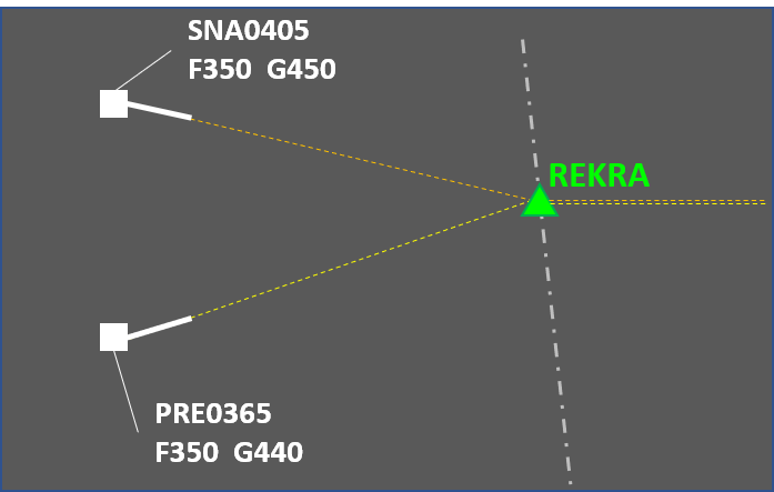
The second and the third situation usually happen near the transition between approach and area control. This is where departing aircraft reach their cruising level and arrivals start preparation for the final portion of the flight. The first one is more typical to the cruising part of the flight.
Action to be taken by the controller in order to eliminate the risk of separation breach depends on a number of factors such as the type of conflict, the specific circumstances, the available aircraft performance, controller workload, etc. The most common methods for solving conflicts are:
-
Level change. This solution is typically used for conflicting aircraft in level flight. In the crossing case, an opposite level may be used for a short time and then the aircraft will climb again to its cruising level. This is not an option in the converging scenario, meaning that the level change needs to be at least 2000 feet. Sometimes it is possible to use opposite levels for converging conflicts but this requires coordination with the downsteam sector or unit.
 An example of using a 1000 ft level change to solve a crossing conflict
 -
Speed control. This method is mostly suitable for solving medium-term conflicts (as the instruction takes time to "produce" separation) and for maintaining already achieved separation. A major limiting factor is the typical cruising speed. For example, trying to sequence an AIRBUS A-380-800 behind a BOEING 737-800 would likely be impracticle (though not impossible). Additional factor to consider with speed control is that the results are not as obvious as for example with level change or vectoring. This means that the controller will need to monitor the situation more frequently to make sure that (a) the flight crews comply with the instructions and (b) the speeds are not affected by changing winds. On the other hand, this method normally results in the slighest intervention of the flight plan - the trajectory and vertical profile are not changed.
-
Vectoring. This is a universal method that may solve any conflict unless additional factors (such as airspace restrictions or adverse weather) limit the available headings. This benefit comes at a cost, however - vectoring usually extends the distance flown (and hence, delays the flight). This effect may sometimes be mitigated by providing a direct routing after the conflict has been solved.
-
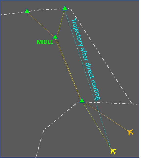
Direct routing. This method is somewhat similar to vectoring because it relies on the aircraft track being changed to an extent where the horizontal separation will no longer be reduced below the minimum. While this method has limited applicability (the results depend mostly on the flight planned route) it often contributes to flight efficiency by reducing the distance to be flown. Other benefits are that the results from the controller intervention are immediately visible and that a single message solves the conflict altogether (unlike with most other methods that follow the instruct-monitor-resume routine). There are some downsides to this solution however, e.g.:
- Depending on the specific circumstances, the flight may enter an area with strong headwinds (which the pilot tried to circumvent with the longer flight planned route).
- In most cases the flight needs to be cleared to a point that is far away which in most cases means a coordination with the next sector or unit will be necessary. This increases controller workload and also adds an element of uncertainty (the next sector controller may not approve the direct routing).
- A direct routing may solve one conflict but create another at the same time.
-
Vertical speed adjustment. This technique is used in situations where an aircraft needs to safely cross another aircraft's level. If properly used, it provides safe and efficient flow of traffic. The rates of climb or descent to be assigned need to be carefully calculated to accomodate some non-compliance (e.g. if the controller assigns a rate of climb of 1500 feet per minute or greater but the aircraft actually climbs at 1300). Also, while descent rates are usually achieveable, climbing at a specified vertical speed may be outside the aircraft capability and therefore the restriction should be coordinated with the flight crew.
A combination of the methods above is sometimes used. Here are some examples:
- Using vectoring to ensure horizontal separation is maintained and assigning vertical speed so that vertical separation is achieved faster (and the vectoring may be terminated sooner). This is useful for separating departing and arriving aircraft.
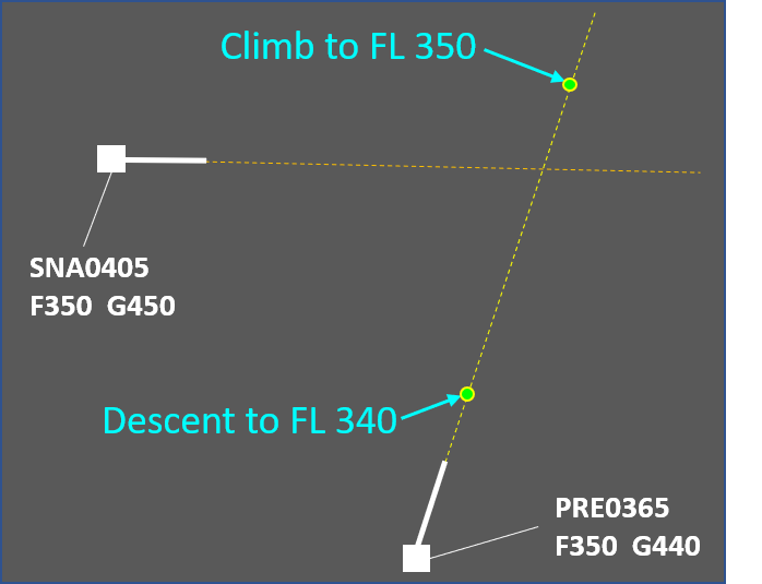
 An example of using vectoring and vertical speed control. Turning PRE0365 provides safety and assigning vertical speeds results in efficiency as the flight can be returned onto the flight planned route sooner.
 - Combining vectoring and speed control may result in a smaller overall intervention as opposed to using vectoring only.
- Combining a direct routing (that makes the converging conflict a crossing one) with a level change. The benefit is that 1000 ft temporary level change may be sufficient as opposed to 2000 feet change for a longer period of time. Note that the direct routing may need to be coordinated.

An example of using a direct route and a level change. Initially, the conflict is of the converging type. By clearing the yellow aircraft to fly on a direct route, the controller does not solve the conflict but now has the option to use 1000 ft level change for a few minutes as opposed to 2000 ft until point MIDLE.
Combined solutions need to be carefully considered. These usually increase the flight crew workload. In some cases the instructions may even be incompatible. An example of this is assigning a high rate of descent to an aircraft that has already been instructed to reduce speed.
Vectoring
This article describes the use of vectoring by air traffic controllers to manage the traffic flow and resolve conflicts. It is focused on the en-route phase and describes the general principles, typical uses and associated risks. The article also gives some advice about the practical use of the vectoring method. Note that the advice is based mostly on good practices and experience, and is in no way intended to replace or supersede local procedures and instructions.
Description
The goal of vectoring is to have the aircraft achieve and maintain the desired track. When an aircraft is given its initial vector diverting it from a previously assigned route, the pilot must be informed about the reason for the deviation (e.g. due to traffic, for sequencing, etc.).
General restrictions:
- Aircraft must not be vectored closer than a half of the separation minimum (i.e. closer than 2.5 NM if the separation minimum is 5 NM) or 2.5NM, whichever is higher, from the limit of the airspace which the controller is responsible for, unless otherwise specified in local arrangements.
- Controlled flights are not to be vectored into uncontrolled airspace, except in the case of emergency or in order to circumnavigate adverse weather (in which case the pilot should be informed), or at the specific request of the pilot.
- When vectoring or giving a direct route to an IFR flight takes the aircraft off an ATS route, the clearance should take into account the prescribed obstacle clearance.
After vectoring, the controller must instruct the pilot to resume own navigation, giving them the aircraft’s position if necessary.
Typical uses
- Flight Identification - while not common in e.g. European airspace, this is one of the few methods for identification available when only primary radar is used.
- Navigation assistance - if due to equipment malfunction other navigation means (e.g. GNSS, INS, RNAV) are not available vectoring remains an option. This can also be useful for strayed VFR flights if the pilot has lost orientation.
- Special use area (SUA) bypassing - if for whatever reason a flight is approaching a SUA (prohibited, restricted, danger, temporary segregated, etc.) and flying above or below it is not feasible then vectoring may be used to guide the aircraft around it.
- Conflict solving (opposite) - if a level change is not possible for some reason (e.g. aircraft unable to climb, conflicting traffic at other levels, need for coordination with other sector, etc.) vectoring can be a very efficient way to solve the situation. A relatively small change of heading is often enough to achieve the desired separation.
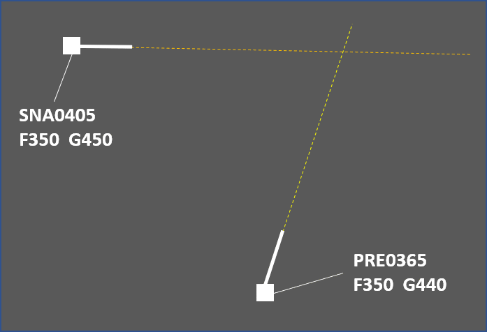
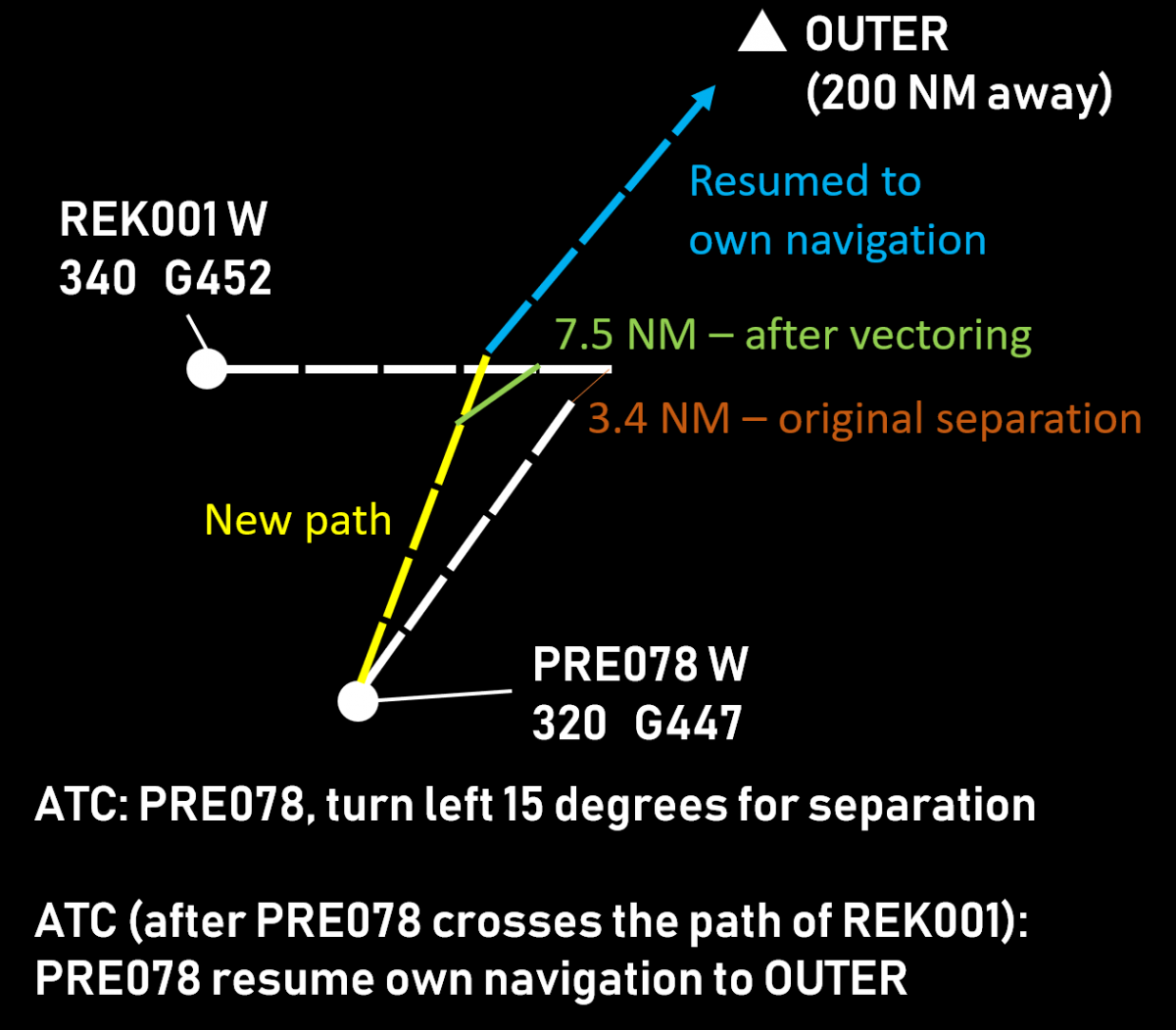
- Conflict solving (crossing) - vectoring is a very effective method for solving crossing conflicts if a level change is not preferable and there is not enough time to perform speed control. In most cases, the aircraft that comes second to the intersection point of the two tracks is instructed to turn in the direction of the first one ("aiming for the other traffic"). This manoeuvre effectively puts the second (or slower) aircraft well beind the first (faster) one. After the crossing is complete, the vectored aircraft may be resumed to point that would compensate for the deviation and the extended flight path, thus gaining both safety and efficiency.

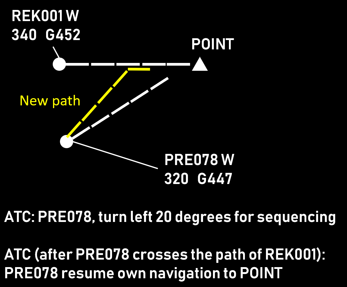
- Sequencing - often combined with speed control, vectoring is an effective method to achieve the desired distance before reaching the boundary with the next ATS sector or unit. The application is similar to the crossing scenario, the difference being that after the desired separation is achieved the aircraft being vectored remains behind the one that is ahead.

Choosing the aircraft
When vectoring is chosen as a means to solve a conflict, the first task of the controller is to decide which aircraft will have to change its heading. Generally, there are three situations:
- Vector both aircraft. This is mostly used to solve conflicts of aircraft on reciprocal (opposite) tracks. This method increases the controller workload (due to having more communication exchanges on the frequency) but offers the benefit of less impact on each aircraft trajectory. Consequently, the increase of the distance flown is usually negligible. While turn direction is determined based on other factors (see next section), the general idea that both aircraft turn, and in the same direction, remains.

- Vector the aircraft that is behind. This is usually used when the two aircraft are maintaining altitude and one is considered to be overtaking the other. This is the more convenient choice from ATC perspective as well, since it requires less intervention (there is already some separation).

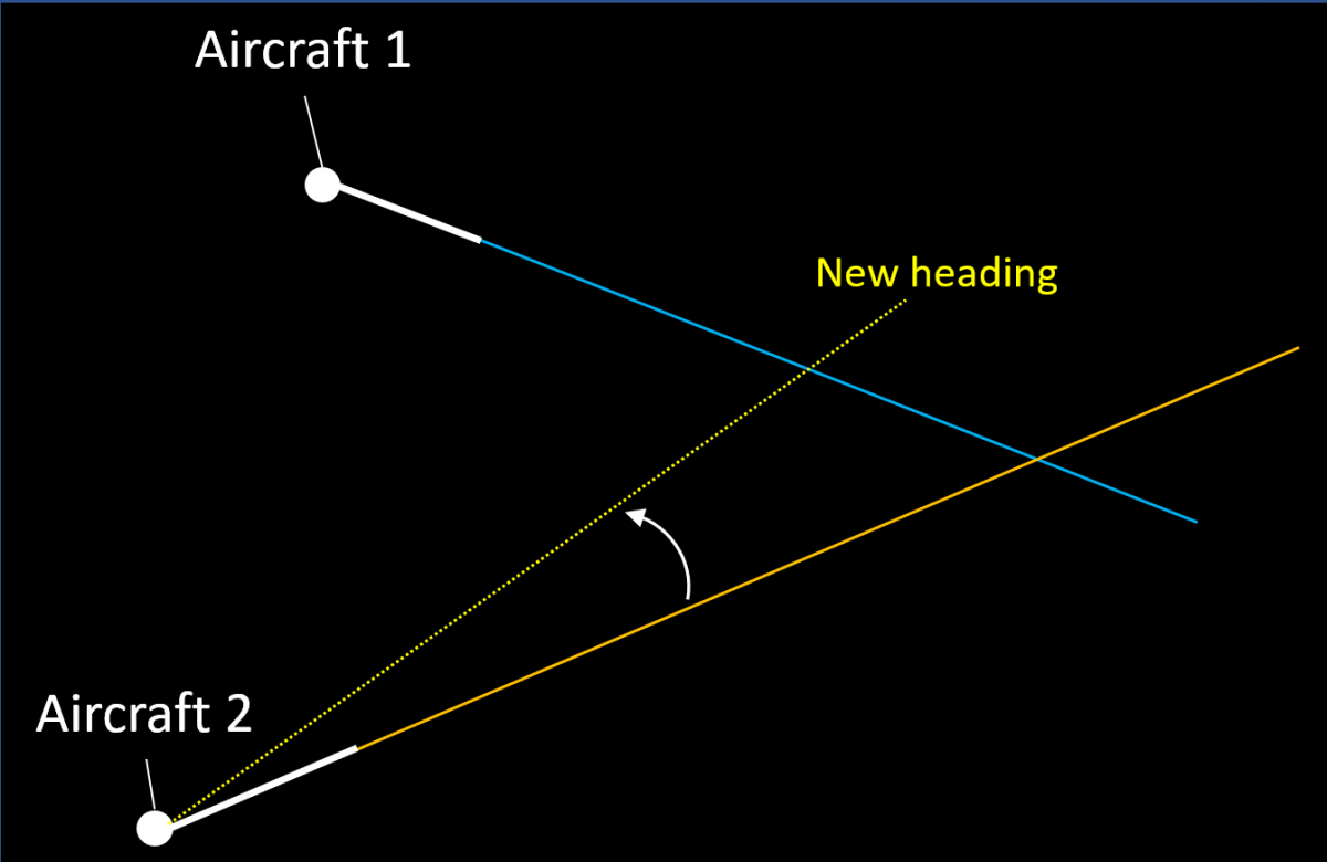
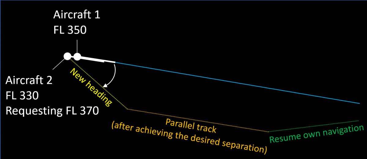
- Vector the requesting aircraft. If a pilot makes a request (usually to climb) and accommodating this request would result in insufficient separation with another aircraft, then the general choice is to vector the requester. Sometimes two vectors are used in such situations - the first one to achieve the desired separation and a second one to maintain it by flying on a parallel track.

Turn Direction
After the aircraft to be vectored has been chosen, the controller decides the direction of the turn. The following general principles are used:
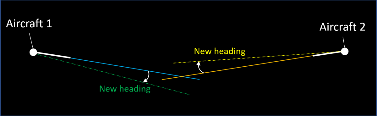
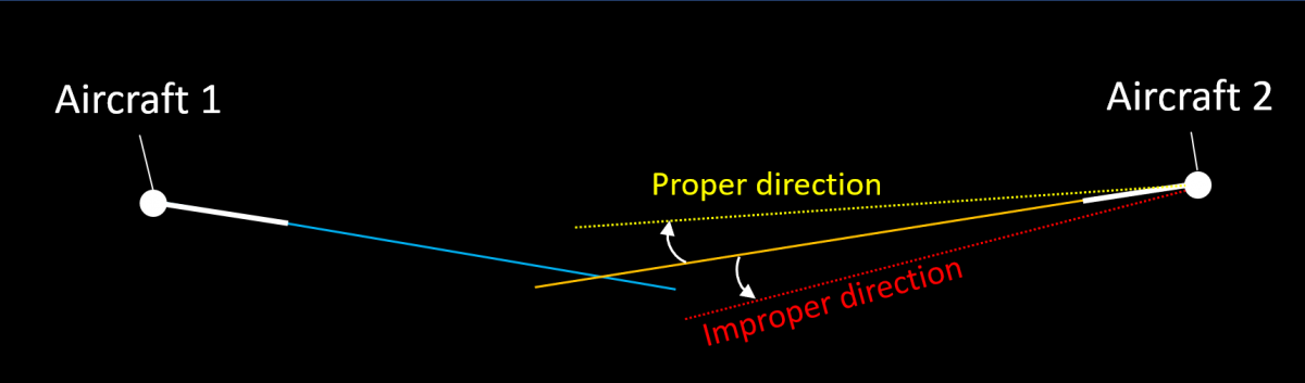
- Aircraft flying on opposite tracks are turned in a direction that would increase the separation.

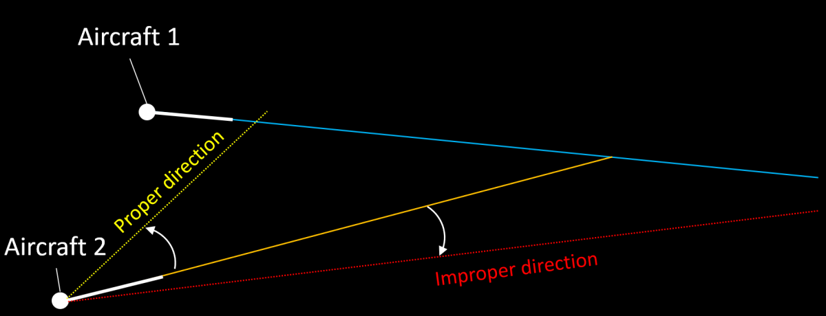
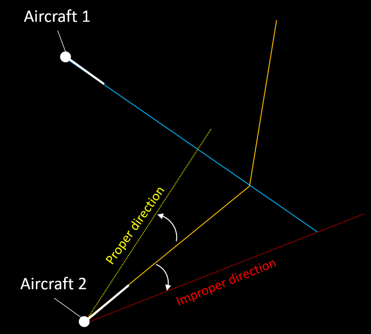
Turning Aircraft 2 slightly to the right is enough to solve the conflict while turning it to the left, even by more degrees, does not. - "Aiming" at the first aircraft's current position. The crossing point is moved in such a way that the distance from the first aircraft is reduced significantly while the distance from the second one is reduced marginally. This results in the second aircraft passing further behind.

Turning Aircraft 2 to the left solves the conflict by placing it behing Aircraft 1. A vector to the right, while prolonging the time to the conflict, does not solve it. - Turning an aircraft against the wind. This reduces the ground speed, effectively placing the aircraft being vectored further behind. In some situations, if the wind is strong enough, vectoring against the wind can be much more effective than speed control for sequencing purposes.

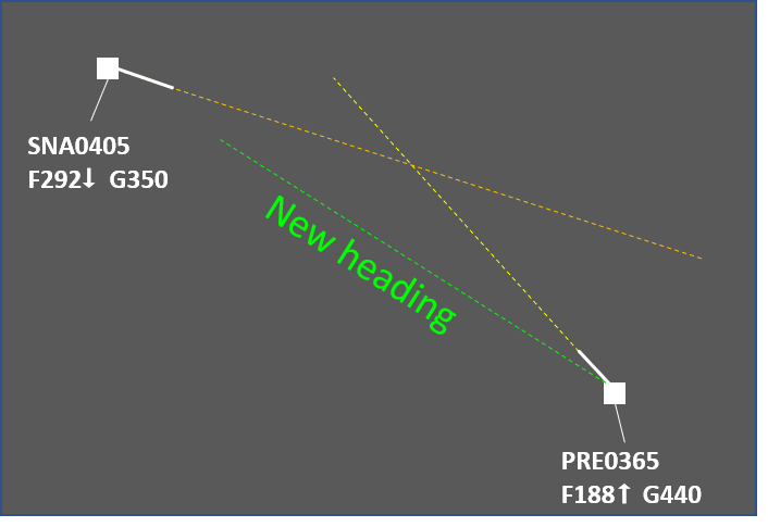
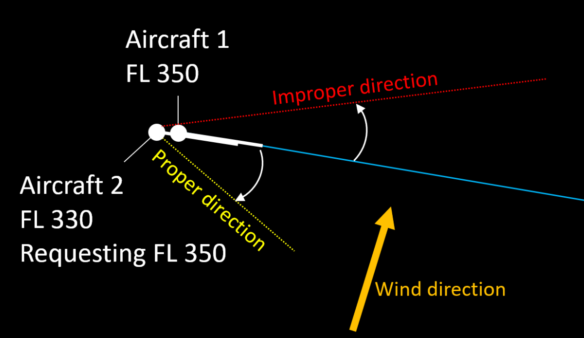
Turning Aircraft 2 to the right allows it to safely climb to FL 350. Due to the speed reduction caused by the wind Aircraft 2 can be sequenced behind Aircraft 1. - Turning in a direction that is in line with the flight planned trajectory is preferable. Thus when the aircraft resumes own navigation its overall flight distance will be only marginally increased and may even be reduced (compared to the flight planned).

Vectoring Aircraft 2 in any direction would solve the conflict but the left turn would not cause a delay. - Turning away from other traffic, special use areas and sector boundaries when practicable. Otherwise additional controller actions may be necessary (e.g. coordination, solving other conflicts, etc.).
Associated Risks
- Forgetting that an aircraft is being vectored. This has a negative impact on flight efficiency but may also "surprise" the next ATS sector or unit, especially if the airway makes a sharp turn at the transfer of control point and the aircraft does not.
- Miscalculation of wind impact (level flight). If a controller tries to sequence an aircraft after another one by vectoring but instructs it to turn so that the tailwind component increses, then the manoeuvre may have no effect (the tailwind will increase the aircraft's speed effectively reducing the expected benefit from vectoring).
- Miscalculation of wind impact (climbing and descending aircraft). Wind may be different at different levels. Even if the direction is somewhat the same, the windspeed can vary significantly. Consequently the headwind/tailwind/crosswind component will also vary and this may impact the desired result. For example, the drifting angle at different levels may be different if the windspeed (and therefore the crosswind component) increases with height. This may lead to parralel tracks becoming converging. A common mitigation for this is to assign a parallel or slightly diverging heading to the aircraft being vectored.
- Miscalculation of aircraft performance (climbing and descending aircraft). Generally, climbing aircraft increase their groundspeed and descending aircraft reduce it. The speed at cruising level can be twice that at e.g. FL 150. If this is not taken into account properly, the result may be loss of separation.
Things to consider
- Crossing point. In most cases vectoring is used to solve crossing conflicts. It is usually most efficient to turn the aircraft that would reach the crossing point later and in the direction of the other aircraft, i.e. if the conflicting traffic is to the left, then the turn should also be to the left. The manoeuvre effectively places the aircraft being vectored behind the other one. If for some reason the first aircraft needs to be vectored, this would require a much larger deviation.
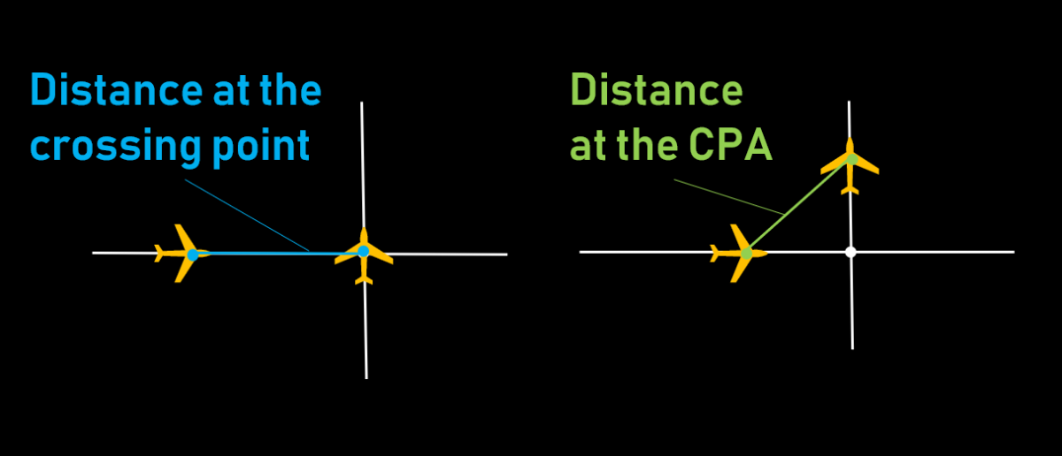
- Closest Point of Approach (CPA). This is the moment when the distance between the two aircraft reaches its minimum. It should be noted that in general, the separation between aircraft continues to reduce for some time even after the first aircraft to reach the crossing point has crossed the track of the second one. The difference between the separation when the first aircraft reaches the crossing point and the moment of CPA depends on the conflict geometry. For example, if the tracks cross at right angle and both aircraft fly at the same ground speed then the separation at the CPA will be about 70% of the separation at the crossing point.

- The sooner, the better. An instruction given well in advance will have (almost) no impact on flight efficiency while solving the situation safely. For example, even a 5 degree heading change would result in about 6 miles displacement to the left/right after 10 minutes. On the other hand, if the conflict is happening after 3-4 minutes, the deviation may need to be 20 degrees or even more in some situations.
- Wind direction and speed. Generally, it is advisable to take advantage of the wind e.g. by turning the second aircraft into the wind to reduce its speed. This may reduce the necessary time an aircraft has to fly on a heading and generally help in resolving the situation faster.
- Aircraft speeds. Vectoring the faster aircraft would result in more spacing after the same amount of time.
- Limitations, e.g. during weather avoidance vectoring may not be a feasible method for conflict solving.
- Track crossing angle. An acute crossing angle means a larger deviation would be necessary to reach the desired separation (compared to a right angle). Generally, the bigger the angle of crossing, the smaller the necessary vector (0 degrees meaning the same direction and 180 - opposite).
- Turn direction. If the instruction "turn left/right heading [ABC]" is used and the present heading is unknown then the manoeuvre performed may surprise the controller (e.g. if the heading is 360 then "Turn left heading 005" would result in the aircraft making an orbit instead of a small turn to the left).
- Misunderstanding. Sometimes it is possible for the flightcrew to confuse instructions like "Turn left 10 degrees" and "Turn left heading 010".
Speed Control
This article describes the use of speed control by air traffic controllers to manage the traffic flow and solve conflicts. It is focused on the en-route phase and describes the general provisions, typical uses and also gives some advice about the practical use of the method. Note that the advice is derived mostly from good practices and experience, and is in no way intended to replace or supersede local procedures and instructions.
Description
Speed control is used to facilitate a safe and orderly flow of traffic. This is achieved by instructions to adjust speed in a specified manner.
Speed adjustments should be limited to those necessary to establish and/or maintain a desired separation minimum or spacing. Instructions involving frequent changes of speed, including alternate speed increases and decreases, should be avoided. Aircraft should be advised when a speed control restriction is no longer required. The flight crew should inform ATC if unable to comply with a speed instruction.
The future position of an aircraft (and, consequently, separation) is determined by the ground speed. Since it is impractical to use it directly, the indicated airspeed (IAS) and Mach number are used instead to achieve the desired ground speed. At levels at or above FL 250, speed adjustments should be expressed in multiples of 0.01 Mach. At levels below FL 250, speed adjustments should be expressed in multiples of 10 kt based on IAS. It is the controller's task to calculate the necessary IAS or Mach number that would result in the appropriate ground speed. The following factors need to be taken into account:
- Aircraft type (range of appropriate speeds)
- Wind speed and direction (in case the two aircraft are not on the same flight path)
- Phase of flight (climb, cruise, descent)
- Aircraft level (especially if the two aircraft are at different levels)
Restrictions on the use of speed control:
- Speed control is not to be applied to aircraft in a holding pattern.
- Speed control should not be applied to aircraft after passing 4 NM from the threshold on final approach.
Phraseology
- Report indicated airspeed / report mach number / speed (in case the current speed cannot be obtained by other means, e.g. Mode S information)
- Maintain/increase/reduce [speed] [or greater/or less] [reason] [condition]. Examples:
- Maintain 300 knots or greater
- Maintain Mach .83 or less due converging traffic until [point name]
- Reduce speed 260 knots or less for sequencing
- Increase speed Mach .82 or greater for the next 10 minutes.
- Resume normal speed (cancels a previously imposed speed restriction)
- No *ATC* speed restrictions (cancels a previously imposed speed restriction)
- On conversion [speed]. This instruction is sometimes used for climbing or descending aircraft when the speed control includes the moment of swithcing between IAS and Mach number. Note: while this instruction is used in a number of countries, it is not part of the ICAO standard phraseology.
Typical Uses
- Separation adjustment (e.g. two successive aircraft are separated by 9 NM and the required separation over the FIR exit point is 10 NM)
- Separation preservation (e.g. two successive aircraft have the necessary separation but this may change if one of them or both change their speed)
- Delay absorption (an alternative to flying a holding pattern)
- Avoid or reduce vectoring:
- in some situations speed control may be used instead of vectoring
- in some situations speed control may be used in combination with a vectoring instruction, in order to reduce the time an aircraft flies on heading and/or the heading change.
Rules of Thumb
- Generally, 0.01 M equals 6 kt
- Speed difference of 6 kt gives 1 NM in 10 minutes
- Speed difference of 30 kt gives 1 NM per 2 minutes
- Speed difference of 60 kt gives 1 NM per minute
Benefits
- Speed control is often the most efficient way for solving conflicts and traffic sequencing.
- The added workload is relatively low, especially for thinner sectors where most level changes need to be coordinated with the neighbouring upper/lower sector.
Things to Consider
- Transition times should be taken into account. It usually takes a few minutes before the aircraft reaches the desired speed due to inertia.
- When an aircraft is heavily loaded and at a high level, its ability to change speed may be very limited.
- Aircraft experiencing turbulence often fly at reduced speed. Under such circumstances it is advisable to coordinate instructions for speed increase with the flight crew.
- Speed control needs more time to achieve the necessary separation compared to other methods (vectoring, level change, vertical speed control). For shorther ATS sectors (e.g. 10 minutes transit time) this method is effective for:
- Separation adjustment (e.g. if the aircraft already have some separation and need a few NM more, this could be achieved by speed control even in shorter ATS sectors)
- Preservation of achieved separation (e.g. if two successive aircraft of similar type already have the nevessary separation, an instruction to maintain the same speed would be appropriate)
- Impact of wind. Winds can make a slower aircraft (in terms of M or IAS) have higher groundspeed than a faster one. In a complex situation, it is usually better to use speed control for successive aircraft and other method (e.g. level change) for a converging conflict.

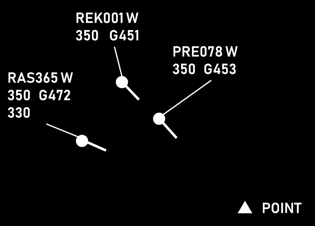
In this situation the three aircraft are of the same type and flying with the same Mach number. However, due to the strong winds, RAS365 is considerably faster. It is therefore advisable to use speed control for PRE078 (e.g. M078 or greater) and REK001 (e.g. M078 or less) and change the level of RAS365 (in this case, descend to FL330). - Maintaining the Mach number during climb (in unchanged wind) results in reduction of TAS (and therefore groundspeed). It is therefore possible that a succeeding aircraft catches up with the preceeding one even if the preceeding aircraft is assigned a higher speed.
- Maintaining IAS during descent (in unchanged wind) results in reduction of TAS (and therefore groundspeed). It is therefore possible that a succeeding aircraft catches up with the preceeding one even if the preceeding aircraft is assigned a higher speed.
- An instruction for speed reduction is generally incompatible with one for maintaining a high rate of descent. Such combinations are best avoided and should only be used after explicit coordination with the flight crew that the desired combination of lateral and vertical speeds is achievable.
- Speed reductions to less than 250 kt IAS for turbojet aircraft should be applied only after coordination with the flight crew.
Vertical Speed
This article describes the use of vertical speed (rates of climb and descend) by air traffic controllers to control the traffic flow and solve conflicts. It describes the general procedures, typical applications and associated risks. It also gives some advice on the use of this method by air traffic controllers. Note that any part of this article is not intended to act as or replace any existing local procedures.
Description
In order to facilitate a safe and orderly flow of traffic, aircraft may be instructed to adjust rate of climb or rate of descent. Vertical speed adjustments should be limited to those necessary to establish and/or maintain a desired separation minimum. Instructions involving frequent changes of climb/descent rates should be avoided.
Climbing/descending aircraft may be instructed to maintain a specified rate of climb/descend, a rate of climb/descent equal to or greater than a specified value or a rate of climb/descent equal to or less than a specified value.
An aircraft may be instructed to expedite climb or descent as appropriate to or through a specified level, or may be instructed to reduce its rate of climb or rate of descent.
Aircraft must be advised when a rate of climb/descent restriction is no longer required. The flight crew must inform the ATC unit concerned if unable, at any time, to comply with a specified rate of climb or descent.
Phraseology
The vertical speed clearance may be a part of a vertical clearance or a separate one. It specifies the required rate of climb/descent, usually in feet per minute and may also contain:
- upper or lower limit of the vertical speed, if applicable. The phrases "or greater" and "or less" are used in this case. If no limit is specified, then the aircraft is expected to maintain an exact vertical speed.
- a condition, if applicable (e.g. until passing a level or a point)
- further information (e.g. reason for the restriction, e.g. traffic, special use area, etc.)
PRE078 climb FL 370 at 1000 feet per minute or greater until passing FL 360 due crossing traffic.
Typical Uses
| Accomodation of climb requests | 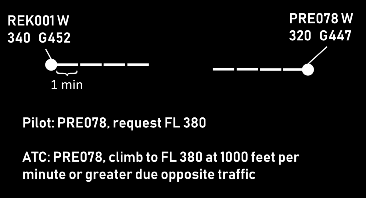 |
| Separation of departing and arriving traffic | 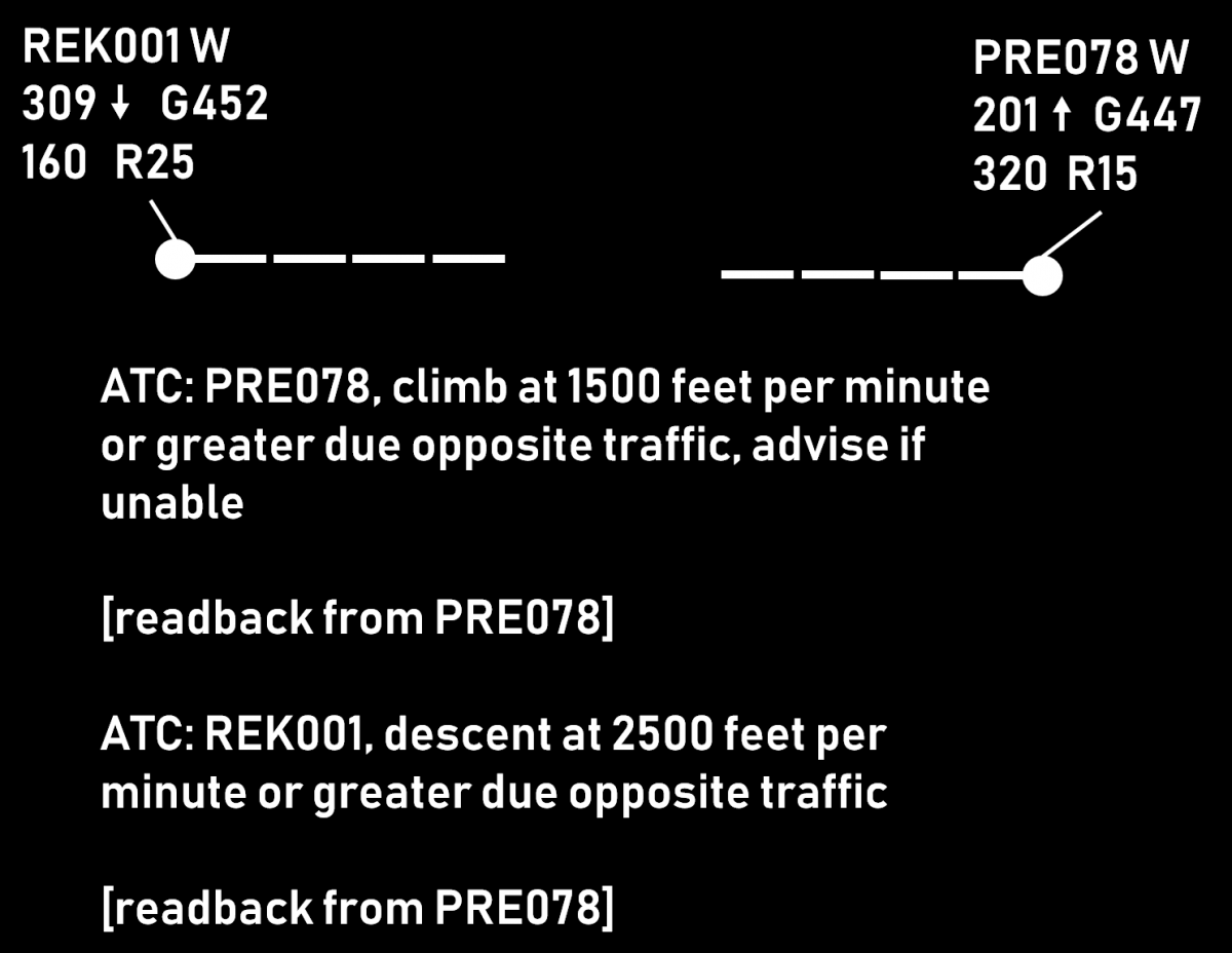 |
| Descending arriving aircraft below the overflying traffic | 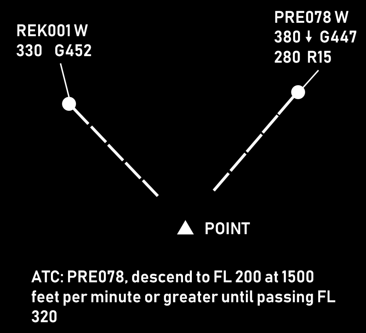 |
| Vertical sequencing, i.e. establishing and maintaining vertical separation between two (or more) climbing or two (or more) descending aircraft | 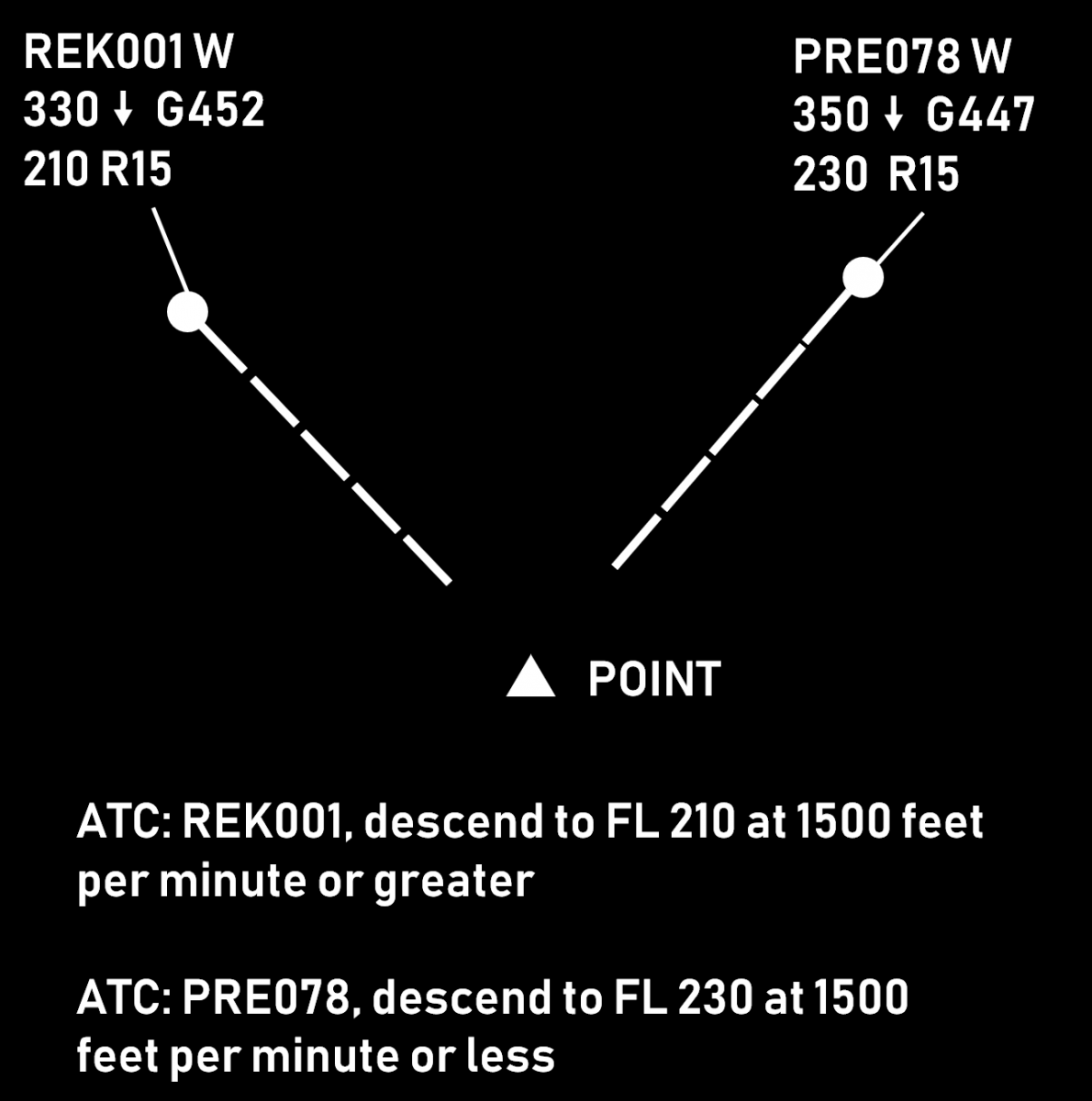 |
| Corrective action (e.g. when the unrestricted vertical speed is considered insufficient) | 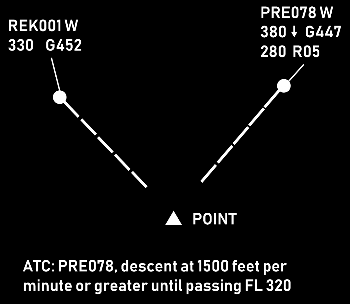 |
Benefits
When properly used, vertical speed control helps to achieve
- continuous climb/descend (fewer level offs), therefore better efficiency
- descents starting close to the top-of-descent
- timely accommodation of climb (mostly) and (sometimes) descent requests
- reduced workload due to reduced need for vectoring. A proper vertical speed ensures that horizontal separation will be preserved at least until vertical separation is achieved.
Associated Risks
- The margin for error is often reduced. This method relies mostly on maintaining vertical separation, which is much smaller than the horizontal one (e.g. 1000 ft as opposed to 5 NM). Therefore, any misunderstanding or non-compliance can easily result in loss of separation.
- Harder to monitor aircraft compliance (as opposed to e.g. vectoring). While the information for vertical speed is usually available, it may require some effort to present it. Furthermore, the interpretation of two (or more) numbers and the comparison of clearances versus performance takes more time than just having a look at the situational display (which is used to monitor horizontal separation).
- Aircraft may be unable to maintain the assigned rate of climb after certain level. If this happens, flight crew may or may not inform the controller.
- Wrong readback may easily ruin the plan (e.g. both aircraft descending with "or greater")
Things to Consider
- Rates of climb should be coordinated with the flight crew, especially:
- when approaching the cruising level
- when the climb is not desired by the flight crew
- when temperatures are high
- Some aircraft types are generally unable to maintain a high rate of climb (e.g. AIRBUS A-321, AIRBUS A-340-300)
- In order to mitigate the risks for crossing or opposite traffic situations, a safety buffer of 1 or 2 minutes should be used. This can be done by e.g.
- Issuing the clearance(s) a bit earlier
- Assigning vertical speeds that are a little higher (e.g. 1500 instead of 1000)
- High rates of descent are generally incompatible with low speeds. A combined instruction to reduce speed and increase the RoD should be coordinated with the flight crew.
- The aircraft needs time to achieve higher rates (2000 ft/min or higher). The transition period should be considered when calculating the necessary vertical speed.
- During the final 1000 ft, the vertical speed is usually 1000 ft/min or less. This is done to avoid level busts. It is therefore impractical to assign a rate of 2000 ft/min or greater if the aircraft is to climb or descend some 2000-3000 ft.
- The phrases "Expedite climb" and "Expedite descent", while being standard ICAO phraseology do not prescribe specific vertical speeds and should be used with caution. The general expectation in such case would be that:
- a climbing aircraft would climb at the highest rate possible (which may or may not be enough to achieve the desired result). It is therefore advisable that larger safety buffers are used or an alternative plan is ready for implementation.
- a descending aircraft would increase the rate of descent to at least 2000 ft/min. It is therefore advisable that this method is used for the first few thousand feet (e.g. for an aircraft at FL 390 "Descend FL 290, expedite passing FL 370 due crossing traffic")
- There should always be an alternative plan to accommodate for an aircraft being unable to continue climb with the desired rate.
Rules of Thumb
- Vertical speed of 2000 ft/min gives 10 FLs in 5 minutes
- Vertical speed of 2500 ft/min gives 10 FLs in 4 minutes
- Combined vertical speed of 4000 ft/min (e.g. RoD 2500 and RoC 1500) gives 20 FLs in 5 minutes
*Combined vertical speed is the sum of the vertical speeds of a climbing and a descending aircraft, e.g. if aircraft A is climbing at 1500 ft/min and aircraft B is descending at 2000 ft/min, then the combined vertical speed is 3500 ft/min.*
Level Change
While there are various reasons for a level change, this article focuses on the conflict solving aspect.
Description
Changing an aircraft's level is often the easiest way for a controller to solve a conflict, i.e. a situation where two (or more) aircraft are expected to be closer than the prescribed separation minima.
Advantages:
- Comparatively smaller intervention. The aircraft continues to fly using own navigation (as opposed to vectoring) and follows the planned route (as opposed to proceeding direct to some distant waypoint).
- Faster to achieve. Even when the aircraft is to climb or descend by 2000 ft, only 1000 are often enough to ensure separation with the conflicting aircraft (see section Opposite Levels for details). This means that the conflict is usually solved within less than a minute.
- Easier to monitor on a situation display. Wind can influence both aircraft speed and flight direction. Additionally, speed vectors can change direction due to specifics of the surveillance system (especially the presence or absence of a tracker). On the other hand, all modern ATS systems provide an indication for climb or descend (an arrow next to the aircraft level). This makes it much easier for a controller to monitor aircraft compliance.
- Less controller workload. Changing an aircraft's level normally requires one instruction and about a minute to achieve the required separation. By contrast, speed control usually requires prolonged monitoring (the required separation "builds up" gradually). Vectoring requires more instructions - at least one for the heading change and one for the return to own navigation but more can be necessary depending on the circumstances. This will also require a longer period of monitoring.
Disadvantages:
- The main disadvantage of a level change is that aircraft normally fly at their optimal cruise levels. Therefore, any level change leads to reduced efficiency. This effect gets worse when increasing the difference between the desired and the cleared level.
- The use of temporary level change (i.e. the aircraft climbs/descends to a safe level to solve a crossing conflict and then returns to its cruising level) requires two vertical movements (one climb and one descend) which is also sub-optimal in terms of efficiency.
- There is an inherent risk of a blind spot, i.e. the controller may solve a medium term (e.g. 15 minutes ahead) conflict while at the same time create a new one with an aircraft just below or above the one being instructed to change level.
- When vertically split sectors are used, the level change may require coordination with an adjacent upper or lower sector which increases the workload for both controllers.
Climb Vs. Descent
After deciding to solve a conflict by a level change, the controller must choose between climb and descent. The former is generally preferred, as it leads to better flight efficiency. However, in some situations descent is the better (or the only) option, e.g.:
- The aircraft is unable to climb due to weight. Note that weight reduces as fuel is burnt so a higher level may be acceptable later. In this case the controller should take into account that the climb rate could be less than usual.
- The aircraft is approaching its top-of-descent. Instructing an aircraft to climb shortly before it would request descent is not very beneficial to flight efficiency and can increase controller workload (the higher the aircraft, the more potential for conflicts during the descent).
- Turbulence is reported at the higher level. Vectoring, direct route or speed control are generally preferable in this situation.
- The manoeuvre is to be performed quickly (e.g. due to a conflict being detected late). In this case, if a climb instruction is issued, it may be declined by the crew, thus losing precious time.
If the controller is in doubt as of which option is preferable (and if both are available), the controller may first ask the pilot (time and workload permitting). The fact that the range of available speeds is reduced at higher levels should also be considered. If the climb is to be combined with a speed restriction, this should be coordinated with the crew beforehand.
Opposite Levels
In many situations a level change would require the aircraft to climb or descend by 2000 feet (so that the new level is appropriate to the direction of the flight). However, sometimes it is better to use an opposite level, i.e. one that is only 1000 feet above/below. This is often a good solution in case of crossing conflicts, i.e. where the paths of the two aircraft only intersect at one point and the level change is expected to be temporary.
- The solution is better in terms of flight efficiency because the aircraft will fly as close as possible to the desired level and the need for vertical movement will be reduced
- The opposite level may happen to be within the own sector, therefore no coordination with an adjacent upper or lower sector would be necessary. This reduces the workload of both controllers and is especially useful when there are multiple, vertically-split sectors.
It should be noted, that a few risks exist with this solution:
- If there is a flight on an opposite track, the normally expected 1000 ft separation would not exist
- In case of radio communication failure, the aircraft may fly at an opposite level much longer than expected and the exact moment of returning to the previous level may not be easy to determine.
The picture below show a situation where the use of opposite level is preferable. The level change will be required for a few minutes only and there is no opposite traffic.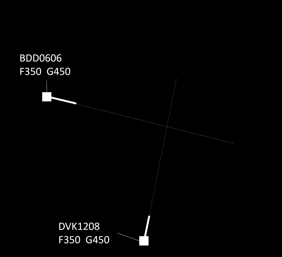
The picture below show a situation where the use of opposite level is not feasible because of opposite traffic. Therefore, a level change of 2000 ft is preferable.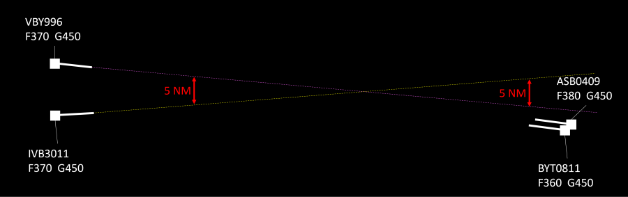
The use of opposite levels can sometimes be justified when the conflict is at the sector exit point. This solution, however, is subject to approval from the downstream controller. The feasibility of this option depends on the geometry of the conflict (are the aircraft diverging after the point of conflict) and on the traffic situation (are there aircraft that are flying at the same level on an opposite track).
Priorities
As a general rule, when two aircraft are at the same cruising level, the preceding aircraft would have priority, i.e. the succeeding aircraft will have to climb or descend. Other criteria may be specified in the manual of operations or other documents containing local procedures. In any case, the controller may deviate from these procedures based on the traffic situation. For example, if changing the level of the succeeding aircraft would create a new conflict (and thus, a new intervention would be necessary), the controller may opt to work with the preceding aircraft. Naturally, flights in distress, or those performing SAR operations, would have priority over other traffic. This includes obtaining (or maintaining) the desired level while a lower priority traffic (e.g. a commercial or general aviation flight) would have to change level. Other priorities may be specified in local procedures (e.g. flights with head of state on board).
Vertical Speed Considerations
Normally, vertical speed is not considered an issue in case of a level change solution to a conflict. This is because in most cases the instruction is issued well in advance (5-15 minutes before the potential separation breach) and the level change is 1000 or 2000 ft, which means that vertical separation will be achieved comfortably prior to losing the required horizontal spacing. Nevertheless, there are some situations where it might be necessary to ensure that the vertical speed will be sufficient. These include:
- There is a reason to believe that the aircraft will not (be able to) climb fast, e.g. a heavy long-haul flight in the initial cruise stage, the aircraft type is known to climb slower than others, the new level is near the ceiling, etc. While 1000 ft/min means that 1000 ft separation will be achieved in one minute, if the rate drops to 200 ft/min, the required time will be 5 minutes. In the scenario where 2000 ft level change is necessary (e.g. converging traffic at the sector exit point and an opposite traffic 1000 ft above), a 200-300 ft/min climb rate will result in a 7-10 minute climb.
- Sometimes, if a descent rate is not specified, the manoeuvre may start at rates in the range of 500 ft/min. In this case, a 2000 ft level change will require 4 minutes as opposed to only 1 or 2 if "normal" vertical speeds of 1000-2000 ft/min are used.
In such situations the controller should either:
- ensure the vertical speed will be sufficient (e.g. by specifying a desired rate of climb or descent), or
- issued the instruction early enough, or
- if the above are not possible, an use an alternative solution.
Source: www.skybrary.aero
Runway Change Guide
Runway changes can improve aerodrome efficiency but require careful coordination to ensure a smooth transition. The Tower controller is responsible for initiating a runway change, ensuring all affected units are informed, and managing the transition effectively. This guide outlines the procedures for a safe and efficient runway change.
Conditions for Runway Changes
A runway change may be necessary due to various factors, including but not limited to:
-
Weather Conditions:
- Significant wind shifts affecting operations.
- Consecutive missed approaches.
- Low Visibility Procedures (LVPs).
-
Operational Considerations:
- Runway equipment availability (e.g., ILS operational status).
- Optimised arrival sequencing for increased efficiency.
Initiating a Runway Change
When a runway change is deemed necessary, the Tower controller must coordinate the following with all relevant ATC units:
- Estimated time of runway change completion.
- Identification of the last departure using the current runway.
- Identification of the last arrival using the current runway
Tower declares the last arrival, but this must be confirmed by Approach (APP), as APP has the final say on arrivals.
The last departure and last arrival must be confirmed with Approach (APP) and Area (ACC) to ensure proper sequencing and spacing.
Aerodrome Procedures
Delivery (DEL)
- Aircraft previously cleared for departures on the old runway must be recleared for the appropriate SID.
- Once this is completed, all new aircraft should be issued clearances for the new runway as prescribed.
Ground (GND)
- Taxiing aircraft:
- The last departure should taxi to the current departure runway.
- All subsequent departures must be held until the last arrival has landed.
- Once the last arrival has landed, departures may taxi to the new runway.
- If Delivery was unable to reclear departures on the new SID, Ground is responsible for ensuring the correct departure clearance is issued.
Tower (TWR)
IFR Procedures
- Coordination with Approach:
- TWR must inform APP when the last arrival/departure is complete, signaling the start of the runway transition.
- The last arrival must be confirmed by APP, as APP has the final say on sequencing.
- The first departure on the new runway requires a release from APP before clearance is issued.
VFR Procedures
- Circuit traffic should be repositioned safely during the transition.
- VFR aircraft must be cleared for circuits on the new runway as soon as operationally feasible.
- Aircraft waiting for departure should be held in a safe area until the transition is complete.
Approach Procedures (APP)
- Once the last arrival has landed, APP must ensure all subsequent arrivals are sequenced for the new runway.
- If necessary, aircraft may be vectored for spacing before approach clearance to the new arrival runway.
- Caution is required: The last departure may not have departed yet, so careful sequencing must be maintained.
- APP must inform ACC when the runway change is complete.
Area Control Procedures (ACC)
- ACC should ensure arriving aircraft are cleared for the correct STAR leading to the new active runway.
- APP should notify ACC when the runway change is complete, allowing controllers to adjust area sequencing as necessary.
Managing Holding and Spacing During a Runway Change
- If traffic is heavy, Approach may identify a gap in arrivals where the runway change can be executed smoothly.
- The last arrivals on the old runway should land close together to minimize disruption.
- If necessary, short-term holding or vectoring may be used to space aircraft correctly before sequencing them to the new runway.
- Coordination between all ATC positions is critical to ensure a smooth transition.
Summary of Key Runway Change Steps
- Runway change is initiated by the Tower controller based on weather and operational factors.
- Tower coordinates with APP and ACC to determine the last departure and last arrival
- Delivery reclears affected departures and issues new runway clearances.
- Ground ensures proper taxi sequencing, holding aircraft as needed.
- Tower coordinates with Approach and obtains release for the first new departure.
- Approach vectors and sequences arrivals for the new runway while monitoring departure status.
- ACC clears aircraft for the appropriate STAR and coordinates with APP.
- APP informs ACC when the runway change is complete to resume normal operations.
Additional Best Practices for Runway Changes
- Advance planning is key—controllers should anticipate spacing issues before initiating the change.
- Clear communication between all controllers ensures a smooth transition.
- Time the first arrival for the new runway so that it reaches final approach shortly after the last arrival on the old runway has landed.
- Do not rush departures—ensure proper sequencing to avoid conflicts.
- Use holding or vectoring sparingly—only if needed to manage sequencing effectively.
Emergencies
An emergency is any situation that poses an immediate risk to an aircraft or its occupants. ATC must provide immediate assistance, unrestricted airspace, and minimal interference from other traffic.
Emergency Declarations
Pilots use the following standard phrases to declare emergencies:
- MAYDAY, MAYDAY, MAYDAY – Distress Call (Immediate assistance required)
- PAN-PAN, PAN-PAN, PAN-PAN – Urgency Call (Serious issue, but not immediate danger)
If unable to communicate verbally, pilots may squawk 7700 and attempt to contact ATC on 121.5 MHz.
Types of Emergency Landings
Forced Landing
A landing is required due to technical failures making continued flight impossible. Landing as soon as possible is the priority.
Common Causes:
- Engine failure or flameout
- Hydraulic or fuel leaks
- Structural damage
Precautionary Landing
A planned landing due to a developing issue that could worsen if the flight continues. These are usually done for safety reasons rather than immediate danger.
Common Causes:
- Landing gear problems (e.g., stuck gear, wheel punctures)
- Medical emergency onboard
Ditching
A forced landing on water, typically due to complete power loss over the ocean or a large body of water.
Common Causes:
- Total engine failure over water
- Fuel exhaustion
Emergency Classifications
Local Standby
The aircraft has a suspected issue that does not prevent a normal landing, but ATC treats it as an emergency.
Common Situations:
- Engine vibrations or failure of one engine in multi-engine aircraft
- Hydraulic issues affecting flaps or brakes
- Landing gear steering failure
- Smoke or odor in the cockpit
- Minor structural damage (e.g., bird strike)
Full Emergency
A serious emergency requiring immediate priority handling due to the risk of an accident.
Common Situations:
- Onboard fire (engine or cabin)
- Landing gear failure
- Flight control failure
- Cabin depressurization
Aircraft Accident
An aircraft accident occurs when an aircraft crashes on or near the airport. Immediate coordination with emergency services is required.
Handling Emergencies as ATC
Key Responsibilities:
- Acknowledge the emergency and confirm the details.
- Separate the emergency aircraft from all other traffic.
- Ensure silence on frequency if necessary.
- Inform and coordinate with relevant ATC units.
- Provide support by offering direct routing, weather updates, etc.
- Give time for pilots to manage the emergency.
The ASSISTED Memory Aid
ATC can use the ASSISTED checklist for structured emergency handling:
- Acknowledge – Confirm the emergency and understand the situation.
- Separate – Establish and maintain safe separation.
- Silence – Limit unnecessary radio transmissions.
- Inform – Notify relevant sectors (e.g., Approach, ACC, Tower).
- Support – Provide assistance (e.g., vectors, direct routing, alternate airports).
- Time – Allow the flight crew to focus on handling the emergency.
- Else, Disconnect – If the emergency disrupts ATC services, the pilot may be instructed to cancel the emergency or disconnect.
VATSIM Emergency Policy
Emergencies on VATSIM are subject to network rules:
- A pilot may only declare an emergency while under ATC service.
- ATC may request a pilot to terminate the emergency at any time.
- If a pilot refuses, they must disconnect.
- Hijackings (squawk 7500) and unlawful acts are strictly prohibited.
- If a pilot refuses to comply, .wallop for a Supervisor.
Emergency Handling by ATC Position
Tower Controller Responsibilities
- Acknowledge the emergency and instruct the pilot to squawk 7700 if necessary.
- Guide the aircraft back for landing (either visual approach or via ATC instructions).
- Coordinate with Approach and ensure they are aware of the emergency.
- Hold or divert other traffic:
- Stop all departures and arrivals.
- Instruct aircraft on the ground or final approach to hold position or go around.
- Keep runways clear for the emergency aircraft.
- Ensure smooth handoff to Approach if required.
Approach Controller Responsibilities
- Provide vectors to the nearest suitable runway.
- Delay or reroute other arrivals if needed.
- Use speed, altitude, or holding instructions to create space.
- Offer a visual or ILS approach depending on weather.
- Coordinate with Tower for priority landing.
Area Control (ACC) Responsibilities
- Direct the aircraft toward the nearest suitable airport.
- Coordinate with Approach and Tower.
- Use altitude or vectoring to ensure safe descent.
- Inform adjacent controllers if necessary.
Emergency Communication Procedures
An emergency call should include:
- Station being called (e.g., "Center, Mayday, Mayday, Mayday")
- Aircraft callsign
- Nature of emergency
- Intentions
- Position, altitude, heading, speed
- Fuel endurance and persons onboard (if relevant)
Example:
Mayday, Mayday, Mayday
Alpha 456, experiencing engine failure.
Request immediate return to airport.
Currently at FL120, heading 270, speed 280 knots.
Fuel endurance: 2 hours, 156 passengers onboard.
Emergency Operations at Multi-Runway Airports
- If multiple runways are available, non-emergency traffic may be moved to a secondary runway.
- This ensures the emergency aircraft has unrestricted access to the preferred runway.
- Delays should be minimized for other traffic while prioritizing the emergency.
Emergency Separation
If, during an emergency situation, it is not possible to ensure that the applicable horizontal separation can be maintained, emergency separation of half the applicable vertical separation minimum may be used. This means that a 1000 ft vertical separation minimum may be reduced to 500 ft and 2000 ft vertical separation minimum may be reduced to 1000 ft. All flight crews concerned must be advised if emergency separation is used.
Identification
Aircraft identification is a fundamental task in air traffic control, ensuring accurate tracking, communication, and coordination between controllers and pilots. Before issuing any ATC clearance in a Surveillance Services environment, an aircraft must be positively identified.
Methods of Identification
Aircraft can be identified using various methods:
- Unique Call Signs – Each aircraft has a unique identifier associated with its flight plan.
- Transponder Codes (SSR) – Squawk codes assigned by ATC for tracking and separation.
- Aircraft Type & Registration – Helps verify aircraft identity, especially in mixed traffic environments.
- ADS-B Data – Automatic Dependent Surveillance–Broadcast, providing real-time aircraft information.
If a pilot selects an incorrect SSR code or transponder mode, ATC must instruct them to correct it.
Radar Identification
Surveillance radar systems provide position, altitude, and speed data, allowing controllers to track and correlate aircraft targets accurately. Radar identification is required before providing ATC services.
When an aircraft leaves radar coverage or enters uncontrolled airspace, controllers must terminate radar service and inform the pilot accordingly.
Level Verification
- Controllers must verify the displayed level information at least once on initial contact.
- The tolerance for verifying accuracy:
- ±200 FT in RVSM airspace
- ±300 FT in non-RVSM airspace
If the displayed altitude exceeds tolerance values:
✔ Ask the pilot to confirm the correct altimeter setting (QNH)
✔ If necessary, instruct the pilot to disable Mode C altitude reporting
Unlike tower controllers, who can visually observe aircraft, radar controllers rely entirely on surveillance data from various systems.
Primary Surveillance Radar (PSR)
How PSR Works
- PSR transmits electromagnetic waves and displays reflections on the radar screen.
- Each reflection represents an aircraft, but PSR does not transmit aircraft identity information.
- Identification must be performed manually using position correlation or maneuver-based methods.
Methods of Identifying Aircraft Using PSR
- Position Reports – Correlating a radar target with a pilot's position report (distance & bearing from a known point).
- Departing Aircraft – Assigning a radar target to an aircraft departing within 1 NM of the runway end.
- Turn Method – Instructing an aircraft to turn by 30° or more and observing the corresponding radar movement.
- Transfer of Identification – Another controller transfers a positively identified aircraft to your control.
Secondary Surveillance Radar (SSR)
How SSR Works
- Unlike PSR, SSR actively interrogates aircraft transponders, which reply with encoded data.
- Provides enhanced aircraft identification, reducing workload and increasing accuracy.
SSR Interrogation Modes
| Mode | Transmitted Data |
|---|---|
| A | 4-digit squawk code |
| C | Pressure altitude |
| S | Callsign, 24-bit aircraft address, selected altitude, speed, etc. |
Modes A and C are often combined as Mode 3A/C.
Methods of Identifying Aircraft Using SSR
✔ Recognition of aircraft callsign in an SSR label
✔ Recognition of an assigned discrete squawk code
✔ Observation of a pilot-acknowledged squawk IDENT activation
✔ Transfer of identification from another controller
The most common method of identification on VATSIM is recognizing the aircraft ID (callsign) in an SSR label. If a pilot is unable to activate their transponder, they can be identified using PSR methods.
Reading and Deviations of Transponder Values
While transponder deviations are less relevant in a simulated environment than in real life, controllers should still monitor transponder readouts for accuracy.
- A flight level is considered "reached," "maintained," or "left" based on the transponder reading.
- A 200-foot tolerance is generally applied on VATSIM.
- Any deviation beyond tolerance should be addressed with the pilot.
Pilots should be reminded to check their QNH settings if an altitude discrepancy is detected.
SSR & ADS-B in ATC Operations
SSR (Secondary Surveillance Radar) vs. ADS-B
SSR and ADS-B (Automatic Dependent Surveillance–Broadcast) are complementary technologies enhancing ATC surveillance:
| Technology | Function |
|---|---|
| SSR | Interrogates aircraft transponders to receive replies |
| ADS-B | Aircraft broadcasts its own position and data automatically |
Transponder Use in Ground Operations
- Before takeoff: The transponder should be turned on before departure.
- At airports with ground movement radar (SMGCS): The correct squawk code should be set before taxiing.
For more details on Surface Movement Guidance and Control Systems (SMGCS), refer to Skybrary.
Controller Responsibilities in Identification
Before Providing ATC Services
✔ Aircraft must be positively identified.
✔ Identification must be confirmed before issuing clearances.
✔ Inform the pilot of radar identification unless the previous sector already identified them.
If Transponder Issues Occur
✔ Instruct the pilot to check transponder settings.
✔ If Mode C data is unreliable, request them to disable altitude reporting.
Loss of Radar Contact
✔ If an aircraft leaves radar coverage, radar service must be terminated and the pilot must be informed.
✔ Procedural separation may be required if radar service is lost.