SOP
- Provision of Air Traffic Service
- Tower Controller
- The Approach Controller
- The Area Controller
- Runway Change Guide
- Emergencies
- Identification
- Phraseology
- IFR
- VFR
- VMC
- Initial Clearance/Clearance To or Out of the Zone
- Traffic circuit
- Delay techniques
- Practice approach/area
- Arrivals/Approach
- Transits & Other Flights
- VFR in Airspace C/D
- Flight Plans
- SVFR and NVFR
- Helicopters
- Meteorology
- Coordination
- AFIS
- Military Procedures
Provision of Air Traffic Service
Tower Controller
Start-up
A start-up clearance is permission from ATC for an aircraft to start its engines, confirming that the airport can accommodate the resulting noise. This clearance indicates that the controller has assessed the surrounding airspace, verified the flight plan, and deemed it safe for the aircraft to begin its departure process. Pilots must request start-up clearance from ATC before starting their engines.
DEL also issues the start-up clearance with the phrase "start-up approved," which permits engine start. However, the pilot must still coordinate the actual starting of the engines with the ground crew. Engine start is not permitted while on stand but may occur after pushback or when the ground crew has deemed it safe on a remote stand. Start-up clearance is only issued if the flight can expect pushback soon.
During heavy traffic scenarios, DEL manages departure capacities by withholding start-up clearances when necessary. This prevents airport capacity from being exceeded by too many aircraft maneuvering on the surfaces of the airport. Effective coordination between all aerodrome controllers is critical for managing departures efficiently.
In many cases, the aircraft will also require pushback to taxi to the departure runway. Start-up and pushback clearances are often issued together, especially when no delays are anticipated. Controllers should ensure that pilots have received the latest ATIS broadcast and the current local QNH before departure. Providing the QNH with the start-up or pushback clearance is often a good practice.
Pushback
After or during start-up clearance, aircraft parked in positions requiring pushback are typically moved onto a taxiway by a tug. Smaller aircraft may use a procedure called "power back," enabling them to push back and taxi out under their own power without the need for a tug.
ATC must specify the pushback procedure, including the direction (e.g., "facing south"). Aircraft handed over from the Ground Controller (GND) should be ready for pushback, having reached their Target Off-Block Time (TOBT). If no obstructions are present, pushback clearance is issued immediately.
| Station | Phraseology |
| Pilot | Marrakech Tower, TVF67MM, stand 7, request pushback. |
| ATC | TVF67MM, Marrakech Tower, pushback approved, face west runway 10. |
| Pilot | Pushback approved, face west runway 10, TVF67MM. |
The pushback direction depends on the aircraft’s location, runway configuration, and apron traffic flow. Pushbacks temporarily block taxiways, so controllers must proactively manage traffic, especially at large airports. If a pushback cannot occur immediately (e.g., due to another aircraft or an inbound taxiing), the pilot should be informed with a “hold position” instruction and, if possible, given a brief explanation of the delay.
In cases where multiple aircraft are ready for pushback, controllers may deviate from the "first come, first served" rule to optimize overall traffic flow. Conditional pushback instructions can also be issued during high traffic volumes, such as when an aircraft must wait for another to pass behind it before pushing back. This approach improves taxiway coordination and efficiency.
Conditional pushback transfers some responsibility to pilots and is particularly helpful when managing multiple aircraft pushing back in close proximity. However, controllers must ensure that all instructions are clear and unambiguous to avoid misunderstandings. Simpler instructions are preferable if there is any uncertainty about pilot comprehension.
Advanced procedures, such as "push and pull," can be used to manage complex scenarios, such as clearing a taxiway quickly or coordinating pushbacks for adjacent aircraft. Controllers should only use advanced techniques if they are comfortable and confident in their ability to manage the situation effectively.
| Station | Phraseology |
| Pilot | Mohammed V ground, RAM800F, stand C8, request pushback. |
| ATC | RAM800F, Mohammed V ground, short pushback approved face south to finish abeam stand C6, runway 35R. |
| Pilot | Short pushback approved face south to finish abeam stand C6, runway 35R, RAM800F. |
Clearance delivery
The aerodrome controller is responsible for issuing an en-route clearance to a departing IFR aircraft before departure. Typically, pilots request en-route clearance prior to start-up.
Standard clearances for departing aircraft must include the following elements:
a) Aircraft callsign
b) Clearance limit, usually the destination aerodrome
c) Designator of the assigned Standard Instrument Departure (SID), if applicable
d) Initial level, unless specified in the SID description
e) Assigned SSR code
f) Additional instructions or information not included in the SID, such as frequency changes
| Station | Phraseology |
| Pilot | Tunis ground, TUX1758, AT72 stand P26, information F, requesting en-route clearance to Palermo. |
| ATC | TUX1758, Tunis ground, cleared to Palermo, CBN3A departure, climb initially altitude 4000ft, squawk 4661. |
| Pilot | Cleared to Palermo, CBN3A departure, climb initially altitude 4000ft, squawk 4661, TUX1758. |
| ATC | TUX1758, correct. |
Taxi
Taxi clearances must include clear and concise instructions to safely guide pilots to the holding point of the departure runway. If a taxi clearance involves crossing a runway, it must explicitly include either a clearance to cross or an instruction to hold short of the runway.
Pilots may be cleared to taxi even if another aircraft ahead of them is not yet ready to taxi. In such cases, the pilot must stop behind the preceding aircraft and only proceed once it moves. For complex taxi routes, dividing the clearance into smaller sections simplifies the pilot's readback and reduces errors, ensuring active ATC monitoring throughout.
Hold short and give-way instructions must be issued to resolve potential ground conflicts, depending on the traffic situation. However, if two aircraft are not in immediate conflict (e.g., sufficient separation at crossing taxiways), explicit instructions may not be necessary but require close monitoring with intervention if needed.
To maintain efficient ground movement and minimize frequency congestion, controllers should use give-way instructions and conditional clearances. Intersection departures can improve sequencing efficiency for Tower controllers. If a pilot is taxiing to a runway intersection, they should be asked if they are able to accept the intersection departure.
Pilots should be handed over to the next position (e.g., TWR) once:
- They are cleared to the handover point (e.g., runway holding point).
- They are free of conflicts (e.g., no unresolved intersections with other aircraft).
- No further instructions are required from the current controller.
Unnecessary stops due to delays in handovers should be avoided. Controllers should regularly scan the airport to identify aircraft ready for handoff.
For unfamiliar pilots or expedited movement, it is helpful to specify directions (e.g., "Turn left onto taxiway Bravo").
Backtrack Procedure:
Backtracking involves an aircraft entering a runway from an intersection, taxiing in the opposite direction of the runway, and proceeding to the runway's beginning. At the end, the aircraft turns around to utilize the full runway length for takeoff. This procedure is often used when no designated taxiway leads to the runway's beginning or when the taxiway is unsuitable for certain aircraft types.
Line-up
A line-up clearance must be issued to departing aircraft before giving a take-off clearance. Line-up clearances can also be issued as conditional clearances, allowing aircraft to line up behind other traffic when appropriate. Efficient use of the frequency is critical, as only one instruction can be given at a time. Controllers must prioritize transmissions to maintain efficiency and reduce delays.
Aircraft must not be permitted to line up and hold on the approach end of a runway-in-use while another aircraft is landing, until the landing aircraft has passed the holding point. Conditional line-up clearances delegate responsibility to the pilot by instructing them to line up behind specific traffic. For this, good visibility is essential, and the pilot must be advised of the traffic involved. If visibility is poor or the intersection angle is too acute (less than 90 degrees), the pilot must first confirm that they can see the relevant traffic.
Conditional clearances can improve frequency efficiency by filling gaps but often take longer to issue than standard line-up clearances. For example, if a landing aircraft is already near the runway threshold or another aircraft has started its take-off run, a standard line-up clearance is usually more appropriate. Multiple simultaneous conditional clearances are only feasible if the restricting aircraft is directly involved in the sequence (e.g., the next aircraft taxiing past the restricted one).
Departures are typically cleared in the order they are ready, but adjustments may be made to optimize efficiency and minimize delays. Factors influencing the sequence include:
- Aircraft type and performance (e.g., jets vs. turboprops)
- Wake turbulence separation requirements (e.g., departing a medium aircraft before a heavy to avoid delays)
- Routes after takeoff (e.g., aircraft on the same SID requiring separation)
- Priority flights (e.g., medical, SAR, or state flights)
Controllers must aim to maintain minimum separation between aircraft to avoid unnecessarily large gaps, as even small delays can significantly reduce departure capacity. Using intersection departures and conditional line-up clearances can further optimize sequencing and frequency usage.
Take-off clearance
Take-off clearance may be issued when there is reasonable assurance that required separation will exist when the aircraft begins its takeoff. Typically, a departing aircraft will not be cleared for takeoff until the preceding aircraft has either crossed the runway end, started a turn, or until all landing traffic is clear of the runway.
Tower controllers are responsible for ensuring that separation is maintained after departure. At aerodromes with procedural approach control, additional separation requirements may apply. The term "takeoff" should only be used in radiotelephony when clearing an aircraft for takeoff or when canceling a take-off clearance.
In certain situations, take-off or landing clearances can be issued even if the runway is not yet clear. However, there must be a high degree of confidence that the runway will be clear when the clearance takes effect. This procedure can reduce frequency load and improve efficiency, especially in high-traffic situations, but requires significant experience and situational awareness.
Reasonable assurance means being confident that the runway will be clear at the appropriate time. For example, if a departure is scheduled to take off before a landing aircraft, the controller can predict whether the runway will be clear when the inbound aircraft reaches the runway threshold. In such cases, a landing clearance may be issued before the departing aircraft has left the runway, provided all separation requirements will be met.
This procedure can also be applied under reduced runway separation. Wake turbulence or radar separation requirements must still be adhered to. While traffic information is not mandatory in these scenarios, providing it can enhance situational awareness for both pilots and controllers.
Landing clearance
An aircraft on final approach or in the process of landing normally has priority over an aircraft intending to depart from the same or an intersecting runway. Landing aircraft will not be permitted to cross the runway threshold until preceding departing aircraft have either crossed the runway end, started a turn, or until all previous landing aircraft are clear of the runway.
The approach controller is responsible for maintaining wake turbulence separation for arriving aircraft. However, wake turbulence separation is not required for VFR traffic; in such cases, ATC should issue a warning (e.g., "Caution wake turbulence").
Landing and Roll-Out Maneuvers:
To expedite traffic, landing aircraft may be instructed to:
- Land beyond the touchdown zone ("long landing").
- Vacate the runway at a specific exit taxiway.
- Expedite vacating the runway.
When issuing roll-out instructions, controllers must consider factors such as aircraft type, runway length, exit locations, reported braking action, and weather conditions. Heavy aircraft should not be instructed to land beyond the touchdown zone.
In certain situations, such as low visibility, pilots may be asked to report when the runway has been vacated. Tower controllers typically receive approaching aircraft from the approach controller at 8–12 NM before the runway. Controllers should issue landing clearance as early as possible. If no conflicting departures exist, clearance should be given immediately upon initial contact.
A pilot must receive landing clearance before crossing the runway threshold (if advised to expect late clearance) or before reaching minimums during an instrument approach. Failure to receive clearance in time will result in the pilot initiating a go-around. The approach controller is responsible for separation until the aircraft crosses the runway threshold. If two approaches are at risk of losing separation, the tower controller must instruct one aircraft (usually the trailing one) to go around before separation is lost. Traffic information may also be provided to improve situational awareness.
Missed approaches
A missed approach must be instructed if separation (wake turbulence or radar) from preceding traffic cannot be ensured, and all other measures (e.g., speed reductions, delegating visual separation) have been exhausted or are impractical.
Reasons for Missed Approaches:
-
Pilot-Initiated:
- Unstable approach.
- Missed touchdown zone.
- TCAS Resolution Advisory (RA).
- Wind shear or thunderstorms on final approach.
- Landing clearance not received.
- Technical issues (e.g., landing gear problems).
-
Controller-Initiated:
- Runway not clear (e.g., preceding aircraft still on the runway).
- Anticipated loss of separation (e.g., simultaneous approaches too close).
Missed approaches are a standard procedure, not an emergency, and all tower controllers must be prepared to handle them calmly and professionally.
Steps to Handle Missed Approaches:
-
Instruct Missed Approach:
Use clear and audible instructions, e.g., "RAM123, go around," repeating if necessary. Briefly explain the reason (e.g., "traffic on runway" or "separation not ensured"). -
Acknowledge Pilot-Initiated Missed Approaches:
Respond with "RAM123, roger." There is no need to instruct the standard missed approach procedure, as this is part of the approach clearance. Avoid sending additional radio messages unless necessary for separation. -
Establish Separation and Provide Traffic Information:
If the missed approach conflicts with other aircraft, provide traffic information and take steps to establish separation:- Radar Vectors: Issue headings to avoid conflicting tracks.
- Altitude Restrictions: Maintain separation by limiting climb/descent to specific altitudes (at least above MVA).
- Visual Reference: In good weather, a pilot can be instructed to maintain visual reference below MVA with a disclaimer (e.g., "Maintain visual reference until passing [MVA]").
-
Coordinate with Approach or Other Stations:
Every missed approach must be coordinated with the approach controller, especially at airports without delegated IFR separation to the tower. If applicable, provide verbal coordination for clarity. -
Inquire About the Reason:
If the missed approach reason is unclear, request the pilot to report it (e.g., "RAM123, report reason for missed approach"). Relevant information, such as wind shear or technical issues, should be passed to following traffic and the approach controller. -
Handoff to Approach:
Once the aircraft is clear of conflicts and the immediate situation is resolved, transfer it back to the approach controller. Ensure the reason for the missed approach is communicated to prevent redundant queries.
The Approach Controller
Sequencing
While the Tower (TWR) controller primarily focuses on departures, the Approach (APP) controller is responsible for managing arrivals, ensuring they are sequenced safely and efficiently. This involves preventing arrivals from being too close together (which could force a go-around due to an occupied runway) or too far apart (which could result in unnecessary airborne holding and increased fuel consumption).
Sequencing can be managed using several key concepts:
- Separation: The minimum vertical or lateral distance required between two aircraft. This includes radar separation and wake turbulence separation, both of which are critical in approach operations.
- Spacing: The desired distance between aircraft on final approach, which depends on factors such as weather conditions, airport layout, traffic volume, and pilot proficiency.
- Compression: A phenomenon that occurs when a leading aircraft reduces speed on final approach while trailing aircraft continue at a higher speed, causing them to close the gap. Controllers must anticipate this effect and adjust spacing accordingly.
For example, if the required spacing on final approach is 7 NM, an additional 1 NM can be added to account for compression, aiming for 8 NM final spacing when no additional wake turbulence separation is required.
The APP controller must consider several factors when determining final approach spacing:
- Airport Layout: The number of runways, their configurations, and operational capabilities.
- Runway Exit Design: High-speed exits allow aircraft to vacate the runway more quickly, reducing spacing requirements.
- Traffic Volume: Depending on demand, priority may be given to either arrivals or departures, requiring close coordination with TWR.
- Low Visibility Procedures (LVPs): Increased spacing is necessary during reduced visibility conditions.
- Ground Situational Awareness: Monitoring ground movements to adjust spacing for optimal traffic flow.
To establish and maintain proper spacing, controllers should first:
- Reduce the speed of trailing aircraft or
- Increase the speed of leading aircraft, then adjust the speeds of other aircraft accordingly.
Aircraft may be assigned specific speed instructions, such as:
-
Maximum speed
-
Minimum clean speed (minimum speed without flaps, speed brakes, or landing gear deployed)
-
Minimum approach speed
-
A specified IAS (Indicated Airspeed)
-
Controllers should avoid instructing aircraft to reduce speed while maintaining a high descent rate, as these maneuvers are often incompatible.
-
Aircraft should be allowed to remain in a clean configuration for as long as possible.
-
Above FL150, turbojet aircraft should not be reduced to less than 220 knots IAS, which is close to their minimum clean speed.
-
On intermediate and final approach, only minor speed adjustments (not exceeding ±20 knots IAS) should be used.
The following speed recommendations ensure efficient sequencing and predictable spacing:
| Distance from Runway | Maximum IAS |
|---|---|
| 15 NM | 250 knots |
| 12 NM | 220 knots |
| 10 NM (Glideslope Intercept) | 200 knots |
| 7 NM | 190 knots |
| 6 NM | 180 knots |
| 5 NM | 170 knots |
| 4 NM | 160 knots |
- Pilots should not exceed 200 knots upon reaching the glideslope (approximately 10 NM out).
- The approach clearance does not cancel speed restrictions, unless explicitly stated by the controller.
- If unsure whether a pilot is aware of the speed restrictions, it is best to reissue them rather than assume the pilot will adjust preemptively.
- Assigning 180 knots to 6 NM can lead to less precise approaches, as different aircraft types decelerate at different rates. Using 160 knots to 4 NM or 170 knots to 5 NM provides more consistency, reducing spacing deviations to around 0.3–0.4 NM.
- When workload increases, reduce aircraft speeds earlier to maintain control over sequencing.
- Avoid shortening aircraft paths too much, as this can disrupt the flow and spacing.
- Use standard speeds consistently to maintain an organized sequence.
- Prioritize situational awareness and proactive adjustments to prevent unnecessary go-arounds.
ATC issues climb and descent clearances to facilitate departures, arrivals, or to help aircraft avoid adverse weather conditions. As a rule of thumb, controllers can estimate that an aircraft descends at approximately 300 feet per NM (or 1,000 feet per 3 NM), commonly referred to as the 3:1 rule.
For example, when guiding an aircraft over the downwind leg, it should not be higher than 8,000 feet abeam the field; otherwise, it will be too high to turn onto a 10 NM final. To compensate for excessive altitude, pilots may adjust their descent rate at their discretion. However, controllers may assign a specific descent rate if necessary—but should act promptly, as even with speed brakes, an aircraft’s descent rate has its limits.
ATC can also manage vertical speed during both climb and descent to ensure separation between successive or crossing aircraft. This is particularly useful in high-traffic scenarios. In TopSky radar, the assigned rate of climb/descent (ARC function) is marked in the aircraft’s radar label.
When issuing an approach clearance, pilots are expected to descend to the published altitude for the approach. If the controller requires a different altitude, this must be explicitly stated.
Vectoring
Radar vectoring is the process of guiding an aircraft using ATC-assigned headings instead of standard IFR procedures (SID/STAR/Instrument Approach). Controllers must adhere to the Minimum Vectoring Altitude (MVA), which ensures obstacle clearance while vectoring aircraft.
When issuing radar vectors, controllers must:
- Inform the pilot of the purpose of the vector and specify the limit of the vector (e.g., "Vectoring for ILS approach Runway 36").
- When terminating vectoring, instruct the pilot to resume own navigation.
- Aircraft must not be vectored closer than half of the separation minimum (i.e. closer than 2.5 NM if the separation minimum is 5 NM) from the limit of the airspace which the controller is responsible for, unless otherwise specified in local arrangements.
- Avoid vectoring aircraft into uncontrolled airspace, except in emergencies or to circumvent severe weather.
- If an aircraft reports unreliable directional instruments, instruct the pilot to make all turns at an agreed rate and to comply with instructions immediately upon receipt.
When vectoring an IFR flight or issuing a direct routing that takes an aircraft off an ATS route, controllers must ensure that prescribed obstacle clearance is maintained at all times until the pilot resumes navigation. If necessary, the minimum vectoring altitude (MVA) must be adjusted for low-temperature corrections.
Radar vectors can be provided in two ways:
- Heading Assignment: e.g., "Turn left heading 180°."
- Relative Turn Instruction: e.g., "Turn right by 10°."
- This should only be used when there is insufficient time to request a specific heading.
If a radar vector is not self-explanatory (e.g., for final approach), the reason should always be provided (e.g., "Turn left heading 180° for spacing").
Important Considerations:
- When an aircraft is already in a turn, avoid ambiguous instructions like "Turn left/right by..." since the aircraft may not know which heading this refers to. Instead, use "Stop turn" if an immediate heading correction is needed.
- For ILS or localizer approaches, vectoring should be within 30° of the final approach course.
- Example: Runway 36 → Heading 330° or 030° for intercept.
RNAV Arrivals and Point Merge System
The Point Merge System is a specific RNAV-based arrival structure that consists of:
- A merging point
- An arc that arriving aircraft follow until further instruction
Controllers issue a "direct to" clearance to the merging point when appropriate. Since the distance from any point along the arc to the merging point remains constant, this method allows for precise sequencing with minimal workload.
While it is important to consider an aircraft's distance from the extended centerline or ILS feather, controllers should avoid relying too heavily on leader lines and the heading tool. These tools can assist in understanding aircraft performance, but developing a holistic approach—including judging headings by eye and using standard headings—will improve overall control of the approach sequence.
Final approach spacing should be measured aircraft-to-aircraft rather than focusing solely on how far an aircraft is from the extended centerline. The key consideration is the relative position of aircraft along the approach path. As the trailing aircraft nears the localizer, the crucial factor is how far ahead the leading aircraft is when determining when to turn the next aircraft onto the localizer.
Ensuring that aircraft intercept at the correct point for their altitude is important. When managing a continuous flow of inbound traffic, controllers should generally aim to establish aircraft outside of 10 miles whenever possible. However, once this baseline is set, the relative positioning of aircraft matters more than their absolute distance from the localizer.
- Relative Speed Matters: Instead of only checking how far an aircraft is from the extended centerline, focus on its speed relative to the aircraft ahead.
- Perpendicular Base Leg Advantage: Using a perpendicular base leg can help maintain consistent spacing and improve sequencing.
- Avoid Fixation on Identical Intercept Points: Aircraft do not need to intercept at exactly the same point every time. The focus should be on maintaining appropriate spacing between aircraft.
- Localizer Turn Spacing: When an aircraft is a reasonable distance from the extended centerline, its turn onto the localizer will naturally create around 1 NM of spacing. Therefore, aircraft should typically be turned 1 NM before reaching the required spacing down the ILS.
Consistency is key when assigning intercept headings. In still wind conditions, a 30-degree intercept heading should be the standard. Any deviation from this should have a clear justification, such as:
- The aircraft is closer or further from the ILS feather than usual, requiring an adjustment to establish them at an appropriate point for their altitude (typically within ±5°).
- The controller needs to increase spacing by assigning a wider intercept heading or reduce spacing by using a tighter intercept heading (again, usually within ±5°).
- Wind conditions require an adjustment to maintain a true 30-degree track to the ILS.
The previous section highlighted the usefulness of the base leg, but it is important to emphasize its role in maintaining efficient sequencing. The next aircraft must always be ready to turn onto final when required.
- Once the required spacing down the approach is achieved, the following aircraft should be positioned correctly relative to the extended centerline, ready to be turned onto final.
- If an aircraft is on a non-perpendicular base leg, heading away from the airport, it becomes harder to judge spacing along the ILS. The turn toward the localizer will take longer, creating more than a mile of additional spacing. In such cases, controllers should initiate the turn earlier than they would for an aircraft on a perpendicular base leg.
- However, if an aircraft is already in position for final, there is no need to extend them onto a base leg—simply turn them onto final immediately.
It is also acceptable to issue an intercept heading before the aircraft has fully rolled out on base. This demonstrates good situational awareness and ensures spacing down the ILS is maintained efficiently.
To facilitate a Continuous Descent Approach (CDA), pilots should be informed of their track distance from touchdown along with their initial descent clearance. This helps them plan a smooth and efficient descent.
The easiest way to determine track distance is by counting backward from an aircraft already established on final approach:
- Identify an aircraft already on the final approach course.
- Count backward along the approach path to estimate the distance of aircraft still on base or downwind.
For example, if you are aiming for 7 NM spacing on final approach in a stream of A320s:
- If the leading aircraft is established at 10 NM, then the aircraft on base leg will be at approximately 17 NM.
- The aircraft following that will be at around 24 NM.
For VATSIM operations, it is recommended to add an extra NM to account for the additional track miles flown in turns. So, if targeting 7 NM spacing, plan for 8 NM to ensure a consistent separation.
Wind significantly affects intercept headings, especially at airfields where aircraft establish from both sides of the extended centerline.
Example: East-West Runway with a Northerly Wind
(A wind coming from the north)
- Aircraft establishing from the south will require a wider intercept heading to maintain a 30° intercept track to the runway.
- Aircraft establishing from the north will require a tighter intercept heading to maintain the same 30° intercept track.
Controllers must adjust headings accordingly to ensure consistent and predictable approaches, taking wind direction and strength into account.
Wind conditions can also affect the headings used for a perpendicular base leg, requiring adjustments to ensure proper alignment with the localizer.
Example: East-West Runway with a Westerly Wind
(A wind pushing aircraft to the east)
-
A 360° track may require a heading of 350°–355°.
-
A 180° track may require a heading of 185°–190°.
-
Assess the adjustments needed based on wind direction and strength.
-
Monitor your initial aircraft to see how these adjustments are working.
-
Communicate wind effects during controller handovers to maintain consistency.
If there is a strong headwind on final approach, precise timing of the turn onto final is crucial:
- Once an aircraft is turned onto the intercept heading, its ground speed will decrease due to the headwind.
- Turning the trailing aircraft too early could lead to spacing issues. While speed control may help, its effectiveness is limited.
- Turning the trailing aircraft too late means that traffic turning into a strong headwind will cover more track miles in the turn than in still wind conditions.
When adjusting speeds:
- If an aircraft is slowed to 160 knots to 4 NM (or even 150 to 4 NM) too early, it can significantly affect the aircraft behind.
- Avoid speeding up aircraft to close gaps—it rarely works effectively.
- With a strong crosswind on base leg, consider how it impacts aircraft momentum, even when all aircraft are assigned 180 knots.
Holding Stacks
There are several reasons why holding may be necessary in air traffic management:
- Spacing Management: The approach controller (APP) may be unable to maintain the required spacing between arriving aircraft due to high traffic volume. Holding helps create the necessary separation.
- Runway Closure or Restrictions: If the runway is closed or temporarily unavailable, APP may stop accepting arrivals, requiring aircraft to hold.
- Delay Absorption: Holding is used to manage delays efficiently, preventing congestion in the terminal area.
-
Level Separation: Aircraft in the same holding pattern must always be separated by altitude.
-
Pilot Uncertainty: If a pilot is unfamiliar with holding procedures, ATC must provide clear and detailed hold instructions.
-
Extended Delays: If significant delays are expected, aircraft should be informed as early as possible. When practical, they may be given the option to reduce speed en route to absorb the delay rather than holding.
-
ACC Responsibility: When delays are anticipated, the Area Control Center (ACC) is generally responsible for:
- Clearing aircraft to the holding fix.
- Issuing holding instructions and an expected approach time (EAT) or onward clearance time.
-
APP and TWR Coordination:
- After coordinating with APP, ACC may clear an arriving aircraft to a visual holding location until further advised.
- Similarly, after coordinating with TWR, APP may hold an arriving aircraft at a visual holding location until further advised by Tower.
-
Aircraft are typically held at designated holding fixes, which are usually part of the published approach procedure.
-
At regional airports, designated holding fixes are commonly located along standard arrival routes.
-
If required to maintain a safe and orderly flow of traffic, an aircraft may be instructed to orbit at its present position or at another specified position, provided obstacle clearance is ensured.
The standard holding pattern consists of:
- A racetrack-shaped circuit with turns to the right (unless otherwise specified).
- Inbound and outbound legs, typically flown at standard speeds based on aircraft category.
- A holding fix, which serves as the entry point and reference for the hold.
Controllers should ensure that aircraft are instructed clearly on entry procedures, holding speeds, and altitude assignments to maintain safe and efficient traffic flow.
Aircraft holding at a designated fix or visual holding location should be assigned levels in a way that facilitates an efficient and orderly approach sequence.
- Standard Level Assignment:
- The first aircraft to arrive at the holding fix is typically assigned the lowest level.
- Subsequent aircraft are assigned successively higher levels to maintain safe vertical separation.
The general rule is that the first aircraft to enter the hold is the first to leave, ensuring an orderly flow of traffic.
- If an aircraft has reduced speed to absorb delay, it may lose its priority in the sequence.
- Priority for landing follows standard protocol:
- Emergency aircraft
- HOSP (Medical Flights)
- SAR (Search and Rescue Operations)
- Other aircraft in sequence
Holding patterns are always managed by the Center (CTR) controller. When a holding pattern is required, controllers should:
- Reduce speeds early: Aircraft en route to the holding fix should be slowed to minimum clean speed whenever possible. This minimizes time spent in holding, improving fuel efficiency.
- Maintain 1,000 ft vertical separation between aircraft entering the hold.
- Use descent rates efficiently: Assigning appropriate rates of descent ensures aircraft arrive at the holding fix in a properly sequenced manner, maintaining separation.
When issuing a holding clearance, the following elements should be included:
-
Holding Location:
- "HOLD AT / OVER (significant point, name of facility, or fix)"
-
Altitude Assignment:
- "MAINTAIN / CLIMB / DESCEND (level)"
- (Include any additional instructions if necessary)
-
Expected Further Clearance:
- "EXPECT FURTHER CLEARANCE AT (time)"
- "EXPECT FURTHER CLEARANCE IN (minutes)"
- "EXPECTED APPROACH TIME (time)"
Pilots must always be informed of:
- Where to hold (holding fix)
- At what altitude (assigned level)
- Expected approach time (EAT) if the hold is expected to last more than 20 minutes
For military aircraft (e.g., single- or two-seater jets), an EAT must always be provided, regardless of the 20-minute threshold. These aircraft typically have strict fuel planning and may need to divert directly to an alternate if delays extend beyond expectations.
If a new EAT deviates by 5 minutes or more from the previously issued EAT, the pilot must be informed of the change.
In addition to the standard holding instruction, controllers may issue a detailed holding instruction if necessary. This includes:
- Holding fix
- Assigned holding level
- Inbound magnetic track to the holding fix
- Turn direction (standard is right turns)
- Outbound leg duration or distance (if applicable)
- Below FL140 → 1-minute outbound leg
- At or above FL150 → 1.5-minute outbound leg
- Time at which the flight can be continued or the next clearance can be expected
A general holding instruction is typically sufficient, but a detailed instruction must be given in these cases:
-
The pilot is required to hold using a different procedure than the published one.
-
The pilot reports they do not know the published holding procedure.
-
The pilot must enter a holding pattern at a point with no published holding procedure.
-
In TopSky radar, aircraft callsigns and altitudes can be highlighted in color within holding stacks for better visibility.
-
Holding altitudes should not be excessively high. If a holding stack reaches above FL200, controllers should open a second holding fix at a different location.
-
If an adjacent center sector can no longer accept inbounds due to excessive holding requirements, they must establish a new enroute holding fix to manage the traffic overflow.
Managing aircraft in a holding pattern is straightforward when they are simply circling, but the real challenge begins when approach control (APP) starts accepting arrivals again. At this point, CTR must ensure aircraft exit the holding pattern with proper sequencing, specifically achieving 10 NM spacing before handoff to APP.
- Transferring the entire holding stack to APP is only effective if APP has at least the lowest 3-4 aircraft on their frequency.
- This allows APP to sequence aircraft efficiently without wasting airspace.
- Ideally, CTR manages the exit from holding and only transfers aircraft to APP once spacing is properly established.
- Poor Tactic to Avoid:
- Allowing each aircraft to complete a full hold before handing it off to APP results in random and inefficient spacing, making the 10 NM separation goal purely coincidental.
- Plan Ahead: The next aircraft to exit holding should be instructed well in advance to remain on the outbound leg of the hold, effectively flying a downwind pattern.
- Timing the Turn Back:
- When the aircraft is slightly past the abeam point relative to the preceding traffic (which is already inbound to the fix), issue a turn instruction.
- This ensures the aircraft falls in line behind the preceding aircraft, creating the desired 10 NM spacing.
- Why More Spacing is Needed Compared to ILS Vectoring:
- Aircraft in a holding pattern are typically at a higher altitude and therefore have a higher ground speed (GS).
- Despite flying at approximately 220 KIAS, their true airspeed (TAS) is much higher, requiring additional spacing.
- Maintain a Continuous Flow:
- As soon as an aircraft exits holding and turns back toward the fix, the next aircraft must already be preparing for its exit.
- This ensures smooth and efficient sequencing, preventing gaps or bunching.
Effective holding management requires proactive planning. Controllers must:
- Anticipate spacing requirements before initiating aircraft exits.
- Avoid inefficient full-pattern holds before clearance.
- Use outbound legs strategically to maintain orderly sequencing.
- Coordinate with APP to ensure handoffs occur at the right moment.
Efficiently clearing aircraft from holding patterns requires continuous coordination and proactive level assignments.
-
Follow Up on Cleared Levels Quickly:
- As soon as an aircraft exits the holding pattern, immediately clear the aircraft above it down to the newly available level.
- You can instruct aircraft to report reaching the assigned level, ensuring you can promptly clear the next aircraft above it without delays.
- This process maintains a smooth cascade of aircraft descending through the holding stack.
-
Managing Holding Exits Like ILS Sequencing:
- Similar to feeding aircraft to the ILS, clearing aircraft from a hold requires structured sequencing.
- Think of the holding pattern like a downwind and final approach:
- The outbound leg acts as a downwind.
- The inbound leg leading back to the fix functions as the final approach.
- Aircraft should be instructed to maintain outbound heading in advance—failure to do so can result in significant additional track miles and disrupt sequencing.
Holding should be used only as long as necessary to prevent arrival gaps and ensure smooth traffic flow.
- APP and CTR Coordination:
- APP and CTR must communicate to determine how long aircraft need to be delayed to prevent excessive spacing or an empty arrival queue.
- In many cases, just one lap in the holding pattern (approximately 4 to 5 minutes) is sufficient to restore approach capacity.
- Planning the End of Holding:
- Consider the timing of the last aircraft on final approach at APP to determine when holding should begin to be reduced.
- Taking into account the remaining inbound distance, CTR can strategically reduce holding usage to ensure a continuous flow of arrivals.
The Area Controller
Conflict detection
Definitions
Conflict: Predicted converging of aircraft in space and time which constitutes a violation of a given set of separation minima.
Conflict detection: The discovery of a conflict as a result of a conflict search.
Conflict search: Computation and comparison of the predicted flight paths of two or more aircraft for the purpose of determining conflicts.Source: ICAO Doc 9426
Description
Detecting conflicts between aicraft is an important part of the air traffic controller job and arguably the most complex one. Once a conflict is properly identified the resolution is relatively straightforward - the controller chooses an appropriate method (e.g. level change, vectoring, speed control, etc.), implements the plan and monitors aircraft compliance. If the situation remains undetected, however, this may result in loss of separation, late (and more abrupt) manoeuvres, STCA/TCAS activation or worse.
If all aircraft are assigned different levels, and are not expected to climb or descend, then there are no conflicts. Most commercial operations however take place in the RVSM layer which means that this situation is unlikely. Therefore, normally the first thing to be done in a surveillance environment, is a "same level scan", i.e. looking for aircraft that are maintaining the same level. This initial step identifies aircraft that need further examination. The second phase is to discard the pairs that are "obviously" non-conflicting, e.g. flying at the same speed to the same point with long distance between them, those whose paths do not cross, etc. After that, the minimum distance of the "suspicious" pairs is determined and, if necessary, a plan for solving the conflict is created.
Climbing and descending flights present a special challenge as they require more checks to be done, e.g.:
- Does the current level cause conflicts?
- Will the final level for the sector cause a conflict (within the sector or at the exit point)?
- Will any of the intermediate levels cause a conflict within the sector?
- Will the aircraft be able to reach its planned level before the exit point? If not, will this cause a conflict in the next sector?
These checks may become more complex if the aircraft climbs or descends through a high number of flight levels (e.g. climbing from FL 140 up to FL 360). This results in significant change in groundspeed (due to wind and IAS variations) which hinders precise calculations.
Factors that help controllers detect conflicts are:
- system support (see section below)
- discipline, i.e. performing structured scan of the aircraft that are, or will be under control and evaluation of the impact of each flight profile change
- fixed-route environment. This usually means that there are fixed "hotspots" (normally where airways cross). An experienced controller can often detect a conflict by knowing that when there is an aircraft at point A then if the other one is at point B they will be in conflict at point C.
- recurrent training for non-routine situations
Factors that may cause a conflict to be missed include:
- Strong winds (e.g. 50-100 kt or more). These may alter aircraft speeds in such a way that a BOEING 737-300 becomes faster than a AIRBUS A-380-800 in terms of groundspeed. Also, aircraft flying at different tracks will be affected differently. As a consequence, pairs that seem to be safely separated may be in conflict.
- Free route environment. This means that the "standard" hotspots are no longer relevant and a situation may arise anywhere. While free route generally reduces the number of conflicts it makes them harder to identify.
- "Irregular" aircraft, i.e. such that form a small fraction of the traffic flow and can be overlooked due to e.g. high workload or complacency. Examples of these are non-RVSM aircraft in RVSM space, slow-flying business jets, slow-flying aircraft at lower levels (interfering with arriving and departing aircraft), non-routine situations (e.g. aicraft dumping fuel, military interception), etc.
- Deviation from procedures, e.g. provision of ATS outside the area of responsibility, skipping "unnecessary" coordinations, etc.
- Aircraft avoiding weather are a special challenge, because their behaviour is less predictable and trajectory updates cause increased controller workload. If the controller does not update these, however, system support tools may be less useful.
- Airspace boundaries are areas where conflicts are sometimes detected late. This can be caused e.g. by poor coordination, improper colour representation, etc.
- Blind spots - a controller may examine the future path of an aircraft failing to notice the conflicting one which is just above (or below)
- Improper handover/takeover. The relieving controller normally expects all conflicts to be solved or at least detected and having a planned solution. If this is not the case, or if the controller being relieved fails to pass the information, it is possible that the new controller focuses on the medium and long-term situations and misses a near-term conflict.
Conflict Solving
This article describes the typical methods and controller actions used to solve conflict between aircraft in a surveillance (mostly en-route) environment. Only situations with two participating aircraft are considered. Although more complex scenarios (involving three or more aircraft) do exist, they happen rarely and in most cases can be considered as multiple two-aircraft cases that happen at the same time.
In broader terms, a conflict is a situation where the separation at the closest point of approach will be less than the specified minimum and one of the following exists:
- Two aircraft are flying at the same level. In this case, doing nothing will result in a Loss of Separation. There are two sub-scenarios to this:
- Crossing conflict - the two aircraft's paths cross at some point and diverge afterwards.

- Converging conflict - the two aircraft's paths join at some point and remain the same afterwards, at least for a portion of the flight.

- Crossing conflict - the two aircraft's paths cross at some point and diverge afterwards.
- At least one of the aircraft is climbing or descending to a level that will make it cross the other aircraft's level. In this case, doing nothing may lead to a loss of separation depending on the circumstances (e.g. vertical speed, distance between the aircraft, current vertical separation, etc.)
- The two aircraft are vertically separated but at least one of them needs to be cleared to a level that would cross the other's level (e.g. due to reaching the top of descent). Here, doing nothing will not cause loss of separation. However, improper timing of the instruction to change level may lead to this.
The second and the third situation usually happen near the transition between approach and area control. This is where departing aircraft reach their cruising level and arrivals start preparation for the final portion of the flight. The first one is more typical to the cruising part of the flight.
Action to be taken by the controller in order to eliminate the risk of separation breach depends on a number of factors such as the type of conflict, the specific circumstances, the available aircraft performance, controller workload, etc. The most common methods for solving conflicts are:
-
Level change. This solution is typically used for conflicting aircraft in level flight. In the crossing case, an opposite level may be used for a short time and then the aircraft will climb again to its cruising level. This is not an option in the converging scenario, meaning that the level change needs to be at least 2000 feet. Sometimes it is possible to use opposite levels for converging conflicts but this requires coordination with the downsteam sector or unit.
 An example of using a 1000 ft level change to solve a crossing conflict
 -
Speed control. This method is mostly suitable for solving medium-term conflicts (as the instruction takes time to "produce" separation) and for maintaining already achieved separation. A major limiting factor is the typical cruising speed. For example, trying to sequence an AIRBUS A-380-800 behind a BOEING 737-800 would likely be impracticle (though not impossible). Additional factor to consider with speed control is that the results are not as obvious as for example with level change or vectoring. This means that the controller will need to monitor the situation more frequently to make sure that (a) the flight crews comply with the instructions and (b) the speeds are not affected by changing winds. On the other hand, this method normally results in the slighest intervention of the flight plan - the trajectory and vertical profile are not changed.
-
Vectoring. This is a universal method that may solve any conflict unless additional factors (such as airspace restrictions or adverse weather) limit the available headings. This benefit comes at a cost, however - vectoring usually extends the distance flown (and hence, delays the flight). This effect may sometimes be mitigated by providing a direct routing after the conflict has been solved.
-
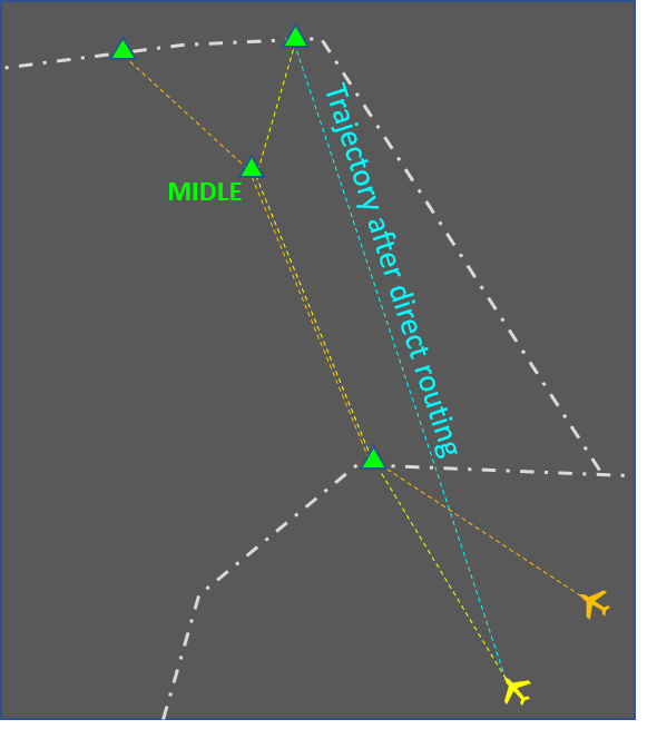
Direct routing. This method is somewhat similar to vectoring because it relies on the aircraft track being changed to an extent where the horizontal separation will no longer be reduced below the minimum. While this method has limited applicability (the results depend mostly on the flight planned route) it often contributes to flight efficiency by reducing the distance to be flown. Other benefits are that the results from the controller intervention are immediately visible and that a single message solves the conflict altogether (unlike with most other methods that follow the instruct-monitor-resume routine). There are some downsides to this solution however, e.g.:
- Depending on the specific circumstances, the flight may enter an area with strong headwinds (which the pilot tried to circumvent with the longer flight planned route).
- In most cases the flight needs to be cleared to a point that is far away which in most cases means a coordination with the next sector or unit will be necessary. This increases controller workload and also adds an element of uncertainty (the next sector controller may not approve the direct routing).
- A direct routing may solve one conflict but create another at the same time.
-
Vertical speed adjustment. This technique is used in situations where an aircraft needs to safely cross another aircraft's level. If properly used, it provides safe and efficient flow of traffic. The rates of climb or descent to be assigned need to be carefully calculated to accomodate some non-compliance (e.g. if the controller assigns a rate of climb of 1500 feet per minute or greater but the aircraft actually climbs at 1300). Also, while descent rates are usually achieveable, climbing at a specified vertical speed may be outside the aircraft capability and therefore the restriction should be coordinated with the flight crew.
A combination of the methods above is sometimes used. Here are some examples:
- Using vectoring to ensure horizontal separation is maintained and assigning vertical speed so that vertical separation is achieved faster (and the vectoring may be terminated sooner). This is useful for separating departing and arriving aircraft.
 An example of using vectoring and vertical speed control. Turning PRE0365 provides safety and assigning vertical speeds results in efficiency as the flight can be returned onto the flight planned route sooner.
 - Combining vectoring and speed control may result in a smaller overall intervention as opposed to using vectoring only.
- Combining a direct routing (that makes the converging conflict a crossing one) with a level change. The benefit is that 1000 ft temporary level change may be sufficient as opposed to 2000 feet change for a longer period of time. Note that the direct routing may need to be coordinated.

An example of using a direct route and a level change. Initially, the conflict is of the converging type. By clearing the yellow aircraft to fly on a direct route, the controller does not solve the conflict but now has the option to use 1000 ft level change for a few minutes as opposed to 2000 ft until point MIDLE.
Combined solutions need to be carefully considered. These usually increase the flight crew workload. In some cases the instructions may even be incompatible. An example of this is assigning a high rate of descent to an aircraft that has already been instructed to reduce speed.
Vectoring
This article describes the use of vectoring by air traffic controllers to manage the traffic flow and resolve conflicts. It is focused on the en-route phase and describes the general principles, typical uses and associated risks. The article also gives some advice about the practical use of the vectoring method. Note that the advice is based mostly on good practices and experience, and is in no way intended to replace or supersede local procedures and instructions.
Description
The goal of vectoring is to have the aircraft achieve and maintain the desired track. When an aircraft is given its initial vector diverting it from a previously assigned route, the pilot must be informed about the reason for the deviation (e.g. due to traffic, for sequencing, etc.).
General restrictions:
- Aircraft must not be vectored closer than a half of the separation minimum (i.e. closer than 2.5 NM if the separation minimum is 5 NM) or 2.5NM, whichever is higher, from the limit of the airspace which the controller is responsible for, unless otherwise specified in local arrangements.
- Controlled flights are not to be vectored into uncontrolled airspace, except in the case of emergency or in order to circumnavigate adverse weather (in which case the pilot should be informed), or at the specific request of the pilot.
- When vectoring or giving a direct route to an IFR flight takes the aircraft off an ATS route, the clearance should take into account the prescribed obstacle clearance.
After vectoring, the controller must instruct the pilot to resume own navigation, giving them the aircraft’s position if necessary.
Typical uses
- Flight Identification - while not common in e.g. European airspace, this is one of the few methods for identification available when only primary radar is used.
- Navigation assistance - if due to equipment malfunction other navigation means (e.g. GNSS, INS, RNAV) are not available vectoring remains an option. This can also be useful for strayed VFR flights if the pilot has lost orientation.
- Special use area (SUA) bypassing - if for whatever reason a flight is approaching a SUA (prohibited, restricted, danger, temporary segregated, etc.) and flying above or below it is not feasible then vectoring may be used to guide the aircraft around it.
- Conflict solving (opposite) - if a level change is not possible for some reason (e.g. aircraft unable to climb, conflicting traffic at other levels, need for coordination with other sector, etc.) vectoring can be a very efficient way to solve the situation. A relatively small change of heading is often enough to achieve the desired separation.
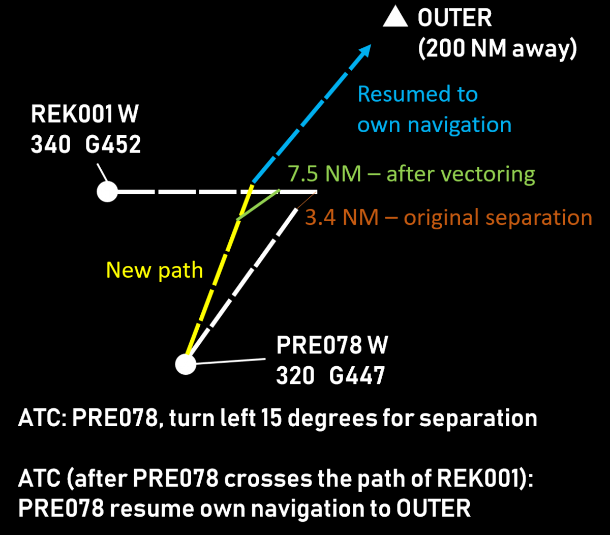
- Conflict solving (crossing) - vectoring is a very effective method for solving crossing conflicts if a level change is not preferable and there is not enough time to perform speed control. In most cases, the aircraft that comes second to the intersection point of the two tracks is instructed to turn in the direction of the first one ("aiming for the other traffic"). This manoeuvre effectively puts the second (or slower) aircraft well beind the first (faster) one. After the crossing is complete, the vectored aircraft may be resumed to point that would compensate for the deviation and the extended flight path, thus gaining both safety and efficiency.

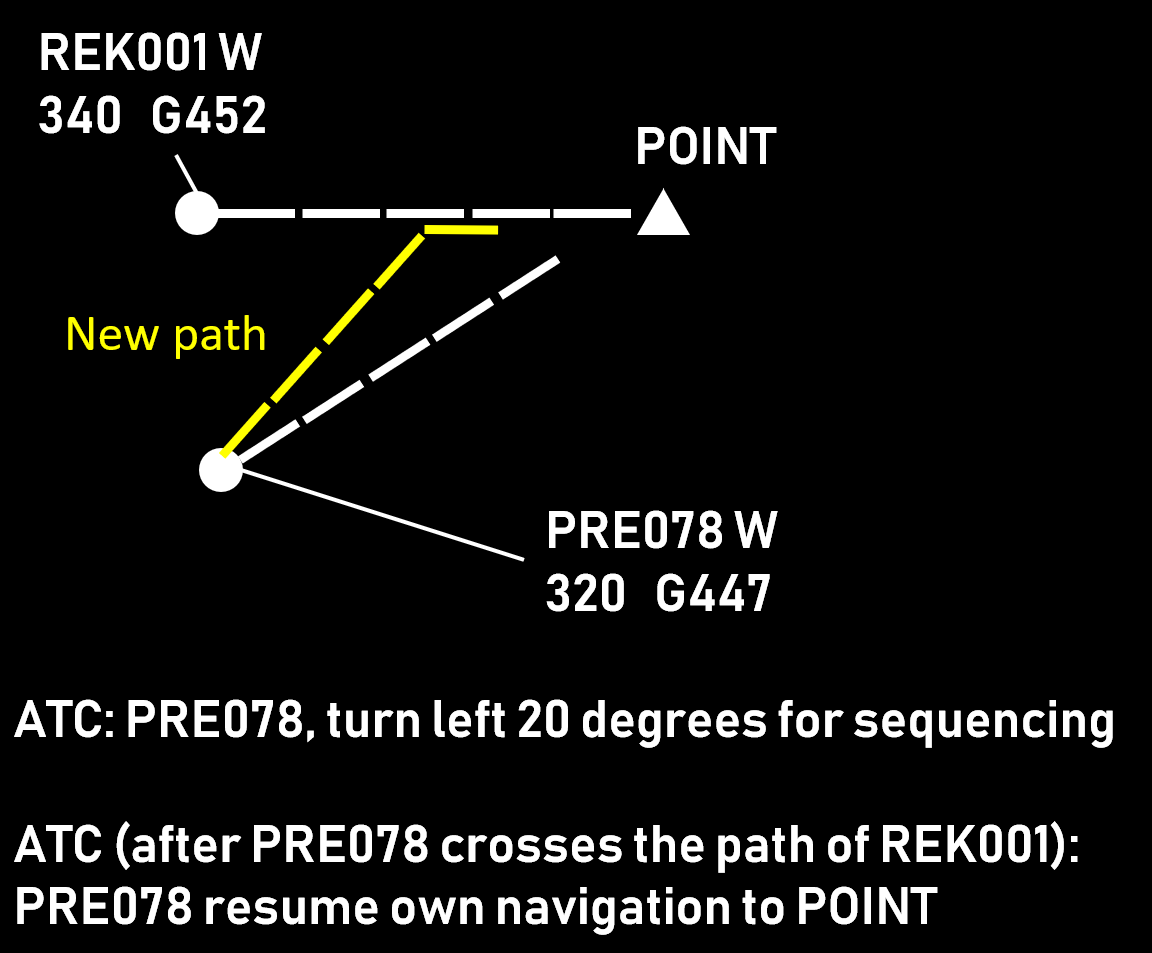
- Sequencing - often combined with speed control, vectoring is an effective method to achieve the desired distance before reaching the boundary with the next ATS sector or unit. The application is similar to the crossing scenario, the difference being that after the desired separation is achieved the aircraft being vectored remains behind the one that is ahead.

Choosing the aircraft
When vectoring is chosen as a means to solve a conflict, the first task of the controller is to decide which aircraft will have to change its heading. Generally, there are three situations:
- Vector both aircraft. This is mostly used to solve conflicts of aircraft on reciprocal (opposite) tracks. This method increases the controller workload (due to having more communication exchanges on the frequency) but offers the benefit of less impact on each aircraft trajectory. Consequently, the increase of the distance flown is usually negligible. While turn direction is determined based on other factors (see next section), the general idea that both aircraft turn, and in the same direction, remains.

- Vector the aircraft that is behind. This is usually used when the two aircraft are maintaining altitude and one is considered to be overtaking the other. This is the more convenient choice from ATC perspective as well, since it requires less intervention (there is already some separation).

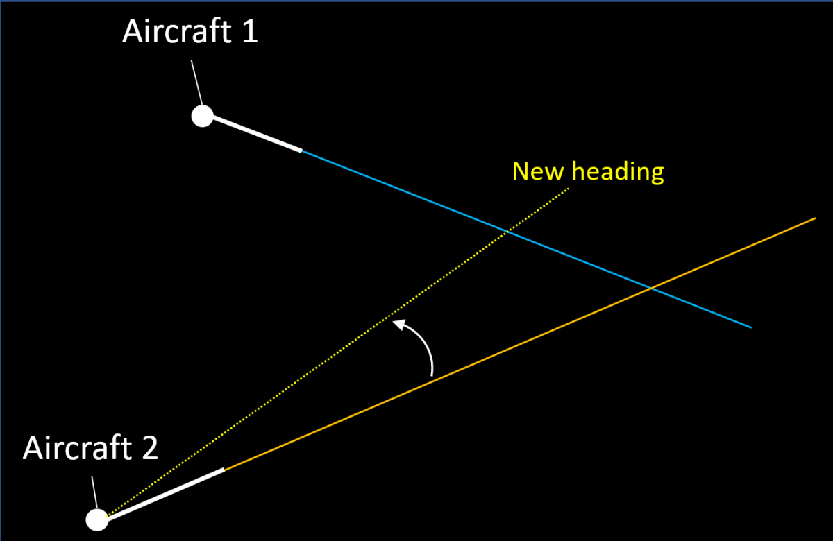
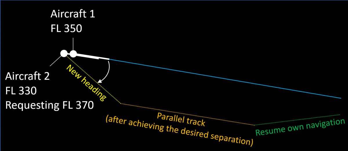
- Vector the requesting aircraft. If a pilot makes a request (usually to climb) and accommodating this request would result in insufficient separation with another aircraft, then the general choice is to vector the requester. Sometimes two vectors are used in such situations - the first one to achieve the desired separation and a second one to maintain it by flying on a parallel track.

Turn Direction
After the aircraft to be vectored has been chosen, the controller decides the direction of the turn. The following general principles are used:
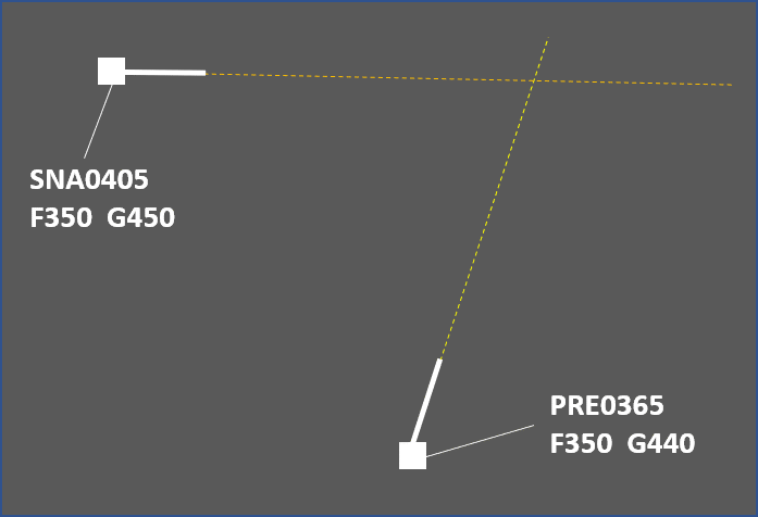
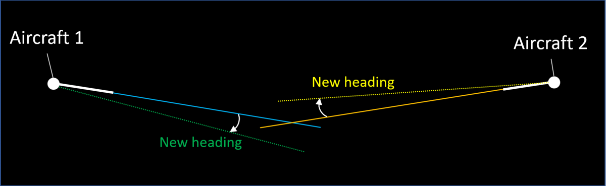
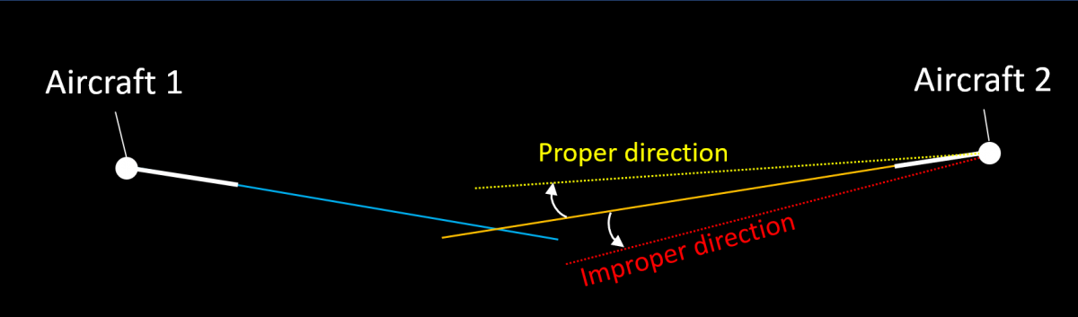
- Aircraft flying on opposite tracks are turned in a direction that would increase the separation.

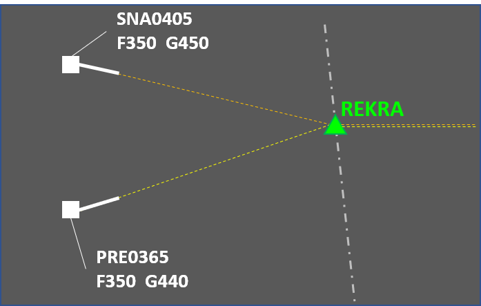
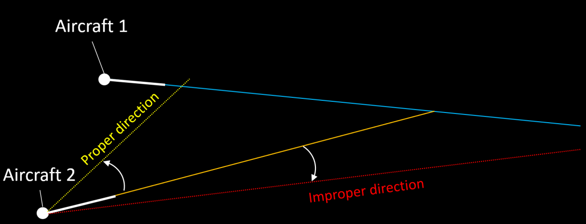
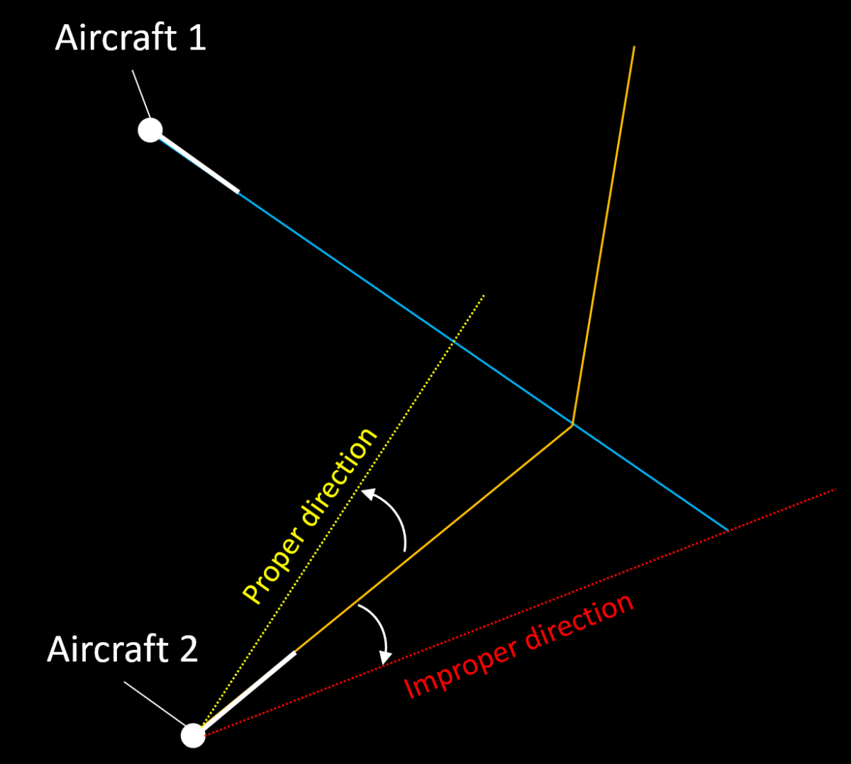
Turning Aircraft 2 slightly to the right is enough to solve the conflict while turning it to the left, even by more degrees, does not. - "Aiming" at the first aircraft's current position. The crossing point is moved in such a way that the distance from the first aircraft is reduced significantly while the distance from the second one is reduced marginally. This results in the second aircraft passing further behind.

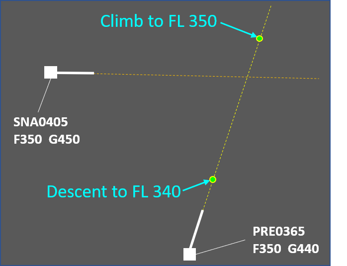
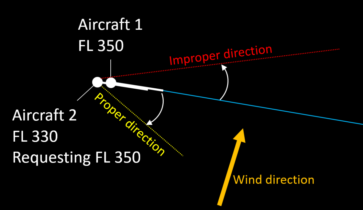
Turning Aircraft 2 to the left solves the conflict by placing it behing Aircraft 1. A vector to the right, while prolonging the time to the conflict, does not solve it. - Turning an aircraft against the wind. This reduces the ground speed, effectively placing the aircraft being vectored further behind. In some situations, if the wind is strong enough, vectoring against the wind can be much more effective than speed control for sequencing purposes.

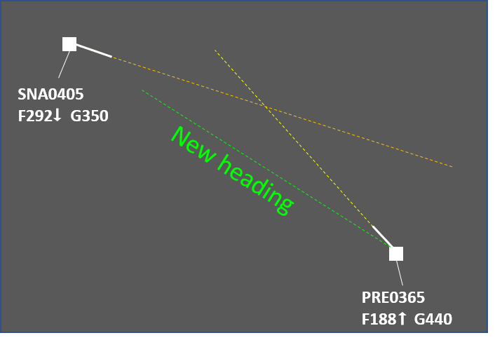
Turning Aircraft 2 to the right allows it to safely climb to FL 350. Due to the speed reduction caused by the wind Aircraft 2 can be sequenced behind Aircraft 1. - Turning in a direction that is in line with the flight planned trajectory is preferable. Thus when the aircraft resumes own navigation its overall flight distance will be only marginally increased and may even be reduced (compared to the flight planned).

Vectoring Aircraft 2 in any direction would solve the conflict but the left turn would not cause a delay. - Turning away from other traffic, special use areas and sector boundaries when practicable. Otherwise additional controller actions may be necessary (e.g. coordination, solving other conflicts, etc.).
Associated Risks
- Forgetting that an aircraft is being vectored. This has a negative impact on flight efficiency but may also "surprise" the next ATS sector or unit, especially if the airway makes a sharp turn at the transfer of control point and the aircraft does not.
- Miscalculation of wind impact (level flight). If a controller tries to sequence an aircraft after another one by vectoring but instructs it to turn so that the tailwind component increses, then the manoeuvre may have no effect (the tailwind will increase the aircraft's speed effectively reducing the expected benefit from vectoring).
- Miscalculation of wind impact (climbing and descending aircraft). Wind may be different at different levels. Even if the direction is somewhat the same, the windspeed can vary significantly. Consequently the headwind/tailwind/crosswind component will also vary and this may impact the desired result. For example, the drifting angle at different levels may be different if the windspeed (and therefore the crosswind component) increases with height. This may lead to parralel tracks becoming converging. A common mitigation for this is to assign a parallel or slightly diverging heading to the aircraft being vectored.
- Miscalculation of aircraft performance (climbing and descending aircraft). Generally, climbing aircraft increase their groundspeed and descending aircraft reduce it. The speed at cruising level can be twice that at e.g. FL 150. If this is not taken into account properly, the result may be loss of separation.
Things to consider
- Crossing point. In most cases vectoring is used to solve crossing conflicts. It is usually most efficient to turn the aircraft that would reach the crossing point later and in the direction of the other aircraft, i.e. if the conflicting traffic is to the left, then the turn should also be to the left. The manoeuvre effectively places the aircraft being vectored behind the other one. If for some reason the first aircraft needs to be vectored, this would require a much larger deviation.
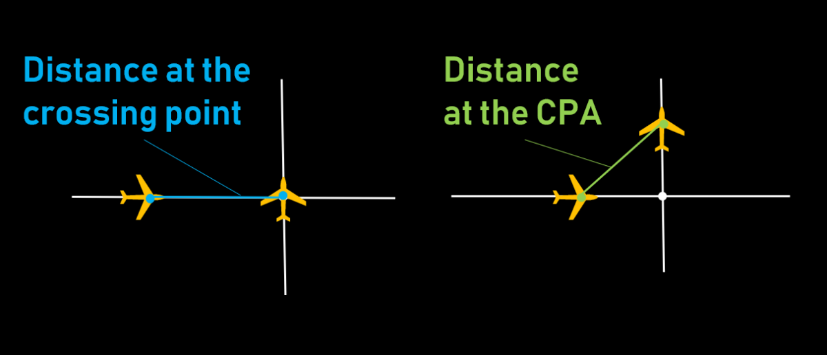
- Closest Point of Approach (CPA). This is the moment when the distance between the two aircraft reaches its minimum. It should be noted that in general, the separation between aircraft continues to reduce for some time even after the first aircraft to reach the crossing point has crossed the track of the second one. The difference between the separation when the first aircraft reaches the crossing point and the moment of CPA depends on the conflict geometry. For example, if the tracks cross at right angle and both aircraft fly at the same ground speed then the separation at the CPA will be about 70% of the separation at the crossing point.

- The sooner, the better. An instruction given well in advance will have (almost) no impact on flight efficiency while solving the situation safely. For example, even a 5 degree heading change would result in about 6 miles displacement to the left/right after 10 minutes. On the other hand, if the conflict is happening after 3-4 minutes, the deviation may need to be 20 degrees or even more in some situations.
- Wind direction and speed. Generally, it is advisable to take advantage of the wind e.g. by turning the second aircraft into the wind to reduce its speed. This may reduce the necessary time an aircraft has to fly on a heading and generally help in resolving the situation faster.
- Aircraft speeds. Vectoring the faster aircraft would result in more spacing after the same amount of time.
- Limitations, e.g. during weather avoidance vectoring may not be a feasible method for conflict solving.
- Track crossing angle. An acute crossing angle means a larger deviation would be necessary to reach the desired separation (compared to a right angle). Generally, the bigger the angle of crossing, the smaller the necessary vector (0 degrees meaning the same direction and 180 - opposite).
- Turn direction. If the instruction "turn left/right heading [ABC]" is used and the present heading is unknown then the manoeuvre performed may surprise the controller (e.g. if the heading is 360 then "Turn left heading 005" would result in the aircraft making an orbit instead of a small turn to the left).
- Misunderstanding. Sometimes it is possible for the flightcrew to confuse instructions like "Turn left 10 degrees" and "Turn left heading 010".
Speed Control
This article describes the use of speed control by air traffic controllers to manage the traffic flow and solve conflicts. It is focused on the en-route phase and describes the general provisions, typical uses and also gives some advice about the practical use of the method. Note that the advice is derived mostly from good practices and experience, and is in no way intended to replace or supersede local procedures and instructions.
Description
Speed control is used to facilitate a safe and orderly flow of traffic. This is achieved by instructions to adjust speed in a specified manner.
Speed adjustments should be limited to those necessary to establish and/or maintain a desired separation minimum or spacing. Instructions involving frequent changes of speed, including alternate speed increases and decreases, should be avoided. Aircraft should be advised when a speed control restriction is no longer required. The flight crew should inform ATC if unable to comply with a speed instruction.
The future position of an aircraft (and, consequently, separation) is determined by the ground speed. Since it is impractical to use it directly, the indicated airspeed (IAS) and Mach number are used instead to achieve the desired ground speed. At levels at or above FL 250, speed adjustments should be expressed in multiples of 0.01 Mach. At levels below FL 250, speed adjustments should be expressed in multiples of 10 kt based on IAS. It is the controller's task to calculate the necessary IAS or Mach number that would result in the appropriate ground speed. The following factors need to be taken into account:
- Aircraft type (range of appropriate speeds)
- Wind speed and direction (in case the two aircraft are not on the same flight path)
- Phase of flight (climb, cruise, descent)
- Aircraft level (especially if the two aircraft are at different levels)
Restrictions on the use of speed control:
- Speed control is not to be applied to aircraft in a holding pattern.
- Speed control should not be applied to aircraft after passing 4 NM from the threshold on final approach.
Phraseology
- Report indicated airspeed / report mach number / speed (in case the current speed cannot be obtained by other means, e.g. Mode S information)
- Maintain/increase/reduce [speed] [or greater/or less] [reason] [condition]. Examples:
- Maintain 300 knots or greater
- Maintain Mach .83 or less due converging traffic until [point name]
- Reduce speed 260 knots or less for sequencing
- Increase speed Mach .82 or greater for the next 10 minutes.
- Resume normal speed (cancels a previously imposed speed restriction)
- No *ATC* speed restrictions (cancels a previously imposed speed restriction)
- On conversion [speed]. This instruction is sometimes used for climbing or descending aircraft when the speed control includes the moment of swithcing between IAS and Mach number. Note: while this instruction is used in a number of countries, it is not part of the ICAO standard phraseology.
Typical Uses
- Separation adjustment (e.g. two successive aircraft are separated by 9 NM and the required separation over the FIR exit point is 10 NM)
- Separation preservation (e.g. two successive aircraft have the necessary separation but this may change if one of them or both change their speed)
- Delay absorption (an alternative to flying a holding pattern)
- Avoid or reduce vectoring:
- in some situations speed control may be used instead of vectoring
- in some situations speed control may be used in combination with a vectoring instruction, in order to reduce the time an aircraft flies on heading and/or the heading change.
Rules of Thumb
- Generally, 0.01 M equals 6 kt
- Speed difference of 6 kt gives 1 NM in 10 minutes
- Speed difference of 30 kt gives 1 NM per 2 minutes
- Speed difference of 60 kt gives 1 NM per minute
Benefits
- Speed control is often the most efficient way for solving conflicts and traffic sequencing.
- The added workload is relatively low, especially for thinner sectors where most level changes need to be coordinated with the neighbouring upper/lower sector.
Things to Consider
- Transition times should be taken into account. It usually takes a few minutes before the aircraft reaches the desired speed due to inertia.
- When an aircraft is heavily loaded and at a high level, its ability to change speed may be very limited.
- Aircraft experiencing turbulence often fly at reduced speed. Under such circumstances it is advisable to coordinate instructions for speed increase with the flight crew.
- Speed control needs more time to achieve the necessary separation compared to other methods (vectoring, level change, vertical speed control). For shorther ATS sectors (e.g. 10 minutes transit time) this method is effective for:
- Separation adjustment (e.g. if the aircraft already have some separation and need a few NM more, this could be achieved by speed control even in shorter ATS sectors)
- Preservation of achieved separation (e.g. if two successive aircraft of similar type already have the nevessary separation, an instruction to maintain the same speed would be appropriate)
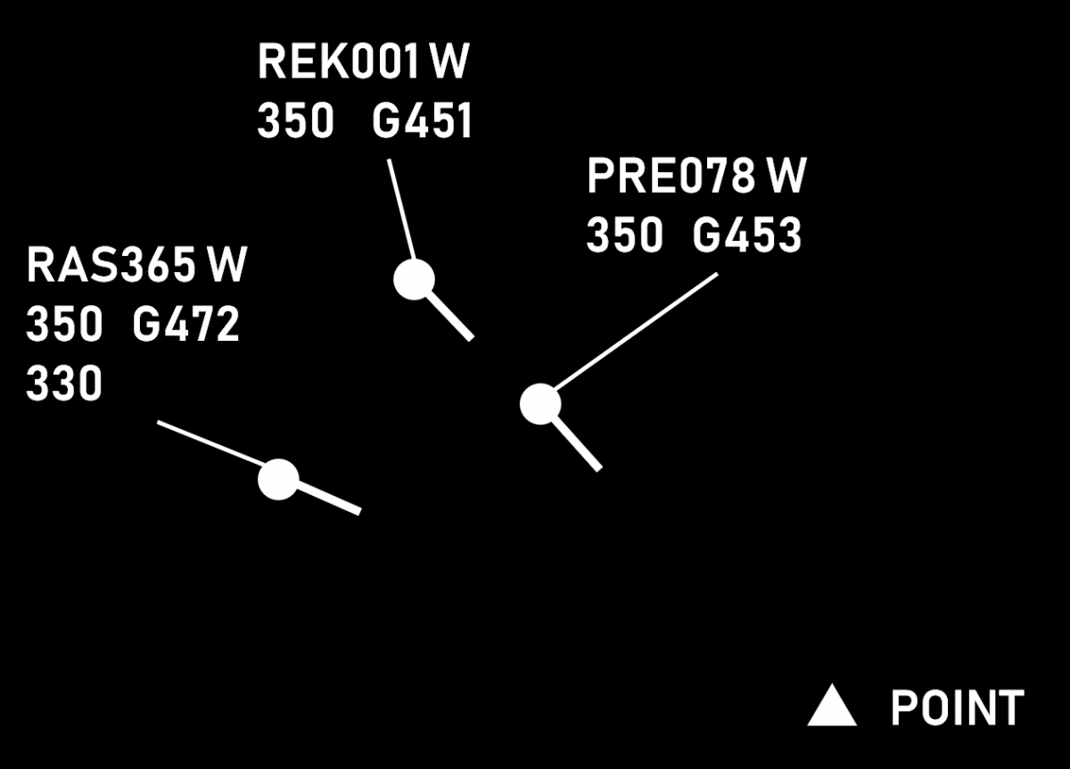
- Impact of wind. Winds can make a slower aircraft (in terms of M or IAS) have higher groundspeed than a faster one. In a complex situation, it is usually better to use speed control for successive aircraft and other method (e.g. level change) for a converging conflict.

In this situation the three aircraft are of the same type and flying with the same Mach number. However, due to the strong winds, RAS365 is considerably faster. It is therefore advisable to use speed control for PRE078 (e.g. M078 or greater) and REK001 (e.g. M078 or less) and change the level of RAS365 (in this case, descend to FL330). - Maintaining the Mach number during climb (in unchanged wind) results in reduction of TAS (and therefore groundspeed). It is therefore possible that a succeeding aircraft catches up with the preceeding one even if the preceeding aircraft is assigned a higher speed.
- Maintaining IAS during descent (in unchanged wind) results in reduction of TAS (and therefore groundspeed). It is therefore possible that a succeeding aircraft catches up with the preceeding one even if the preceeding aircraft is assigned a higher speed.
- An instruction for speed reduction is generally incompatible with one for maintaining a high rate of descent. Such combinations are best avoided and should only be used after explicit coordination with the flight crew that the desired combination of lateral and vertical speeds is achievable.
- Speed reductions to less than 250 kt IAS for turbojet aircraft should be applied only after coordination with the flight crew.
Vertical Speed
This article describes the use of vertical speed (rates of climb and descend) by air traffic controllers to control the traffic flow and solve conflicts. It describes the general procedures, typical applications and associated risks. It also gives some advice on the use of this method by air traffic controllers. Note that any part of this article is not intended to act as or replace any existing local procedures.
Description
In order to facilitate a safe and orderly flow of traffic, aircraft may be instructed to adjust rate of climb or rate of descent. Vertical speed adjustments should be limited to those necessary to establish and/or maintain a desired separation minimum. Instructions involving frequent changes of climb/descent rates should be avoided.
Climbing/descending aircraft may be instructed to maintain a specified rate of climb/descend, a rate of climb/descent equal to or greater than a specified value or a rate of climb/descent equal to or less than a specified value.
An aircraft may be instructed to expedite climb or descent as appropriate to or through a specified level, or may be instructed to reduce its rate of climb or rate of descent.
Aircraft must be advised when a rate of climb/descent restriction is no longer required. The flight crew must inform the ATC unit concerned if unable, at any time, to comply with a specified rate of climb or descent.
Phraseology
The vertical speed clearance may be a part of a vertical clearance or a separate one. It specifies the required rate of climb/descent, usually in feet per minute and may also contain:
- upper or lower limit of the vertical speed, if applicable. The phrases "or greater" and "or less" are used in this case. If no limit is specified, then the aircraft is expected to maintain an exact vertical speed.
- a condition, if applicable (e.g. until passing a level or a point)
- further information (e.g. reason for the restriction, e.g. traffic, special use area, etc.)
PRE078 climb FL 370 at 1000 feet per minute or greater until passing FL 360 due crossing traffic.
Typical Uses
| Accomodation of climb requests | 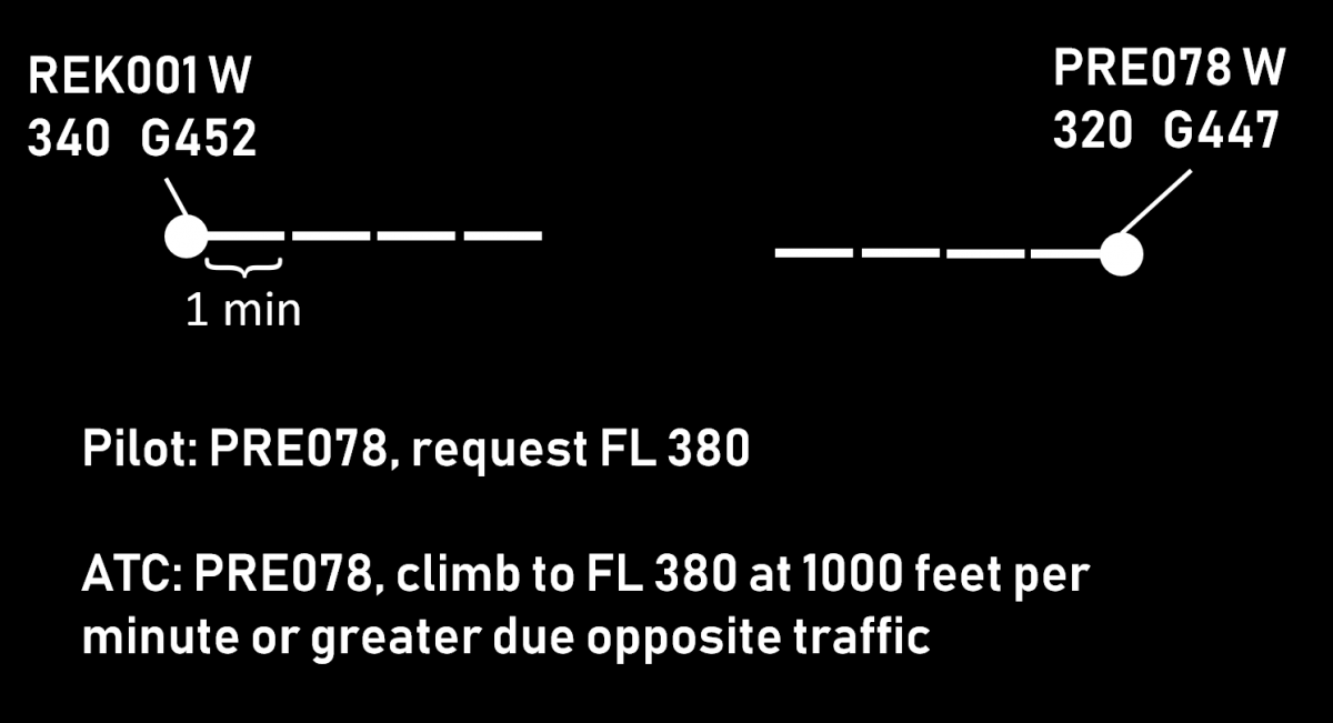 |
| Separation of departing and arriving traffic | 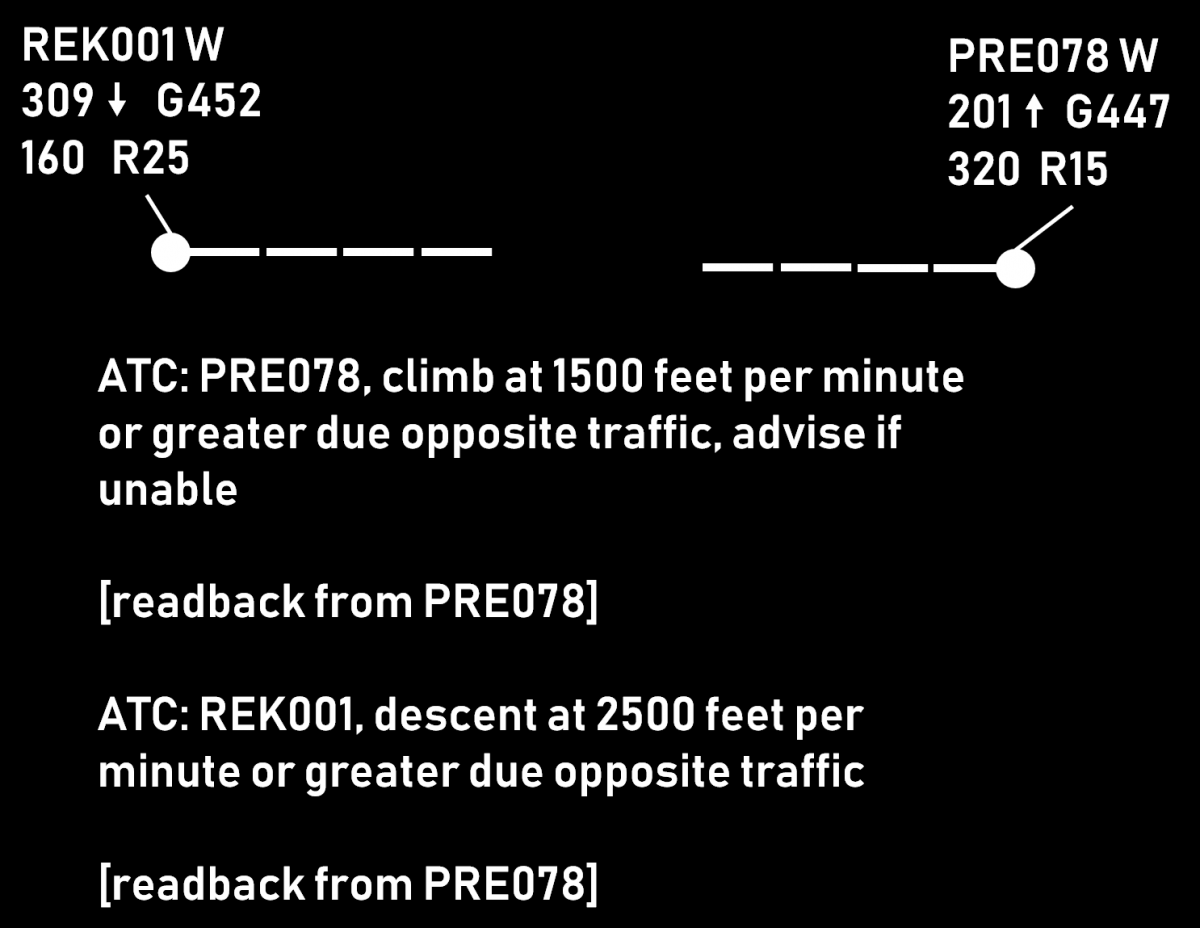 |
| Descending arriving aircraft below the overflying traffic | 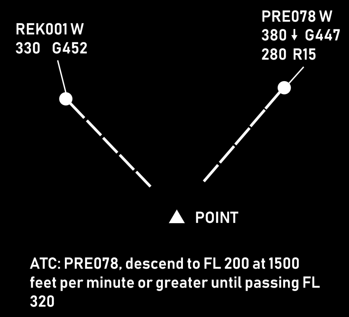 |
| Vertical sequencing, i.e. establishing and maintaining vertical separation between two (or more) climbing or two (or more) descending aircraft | 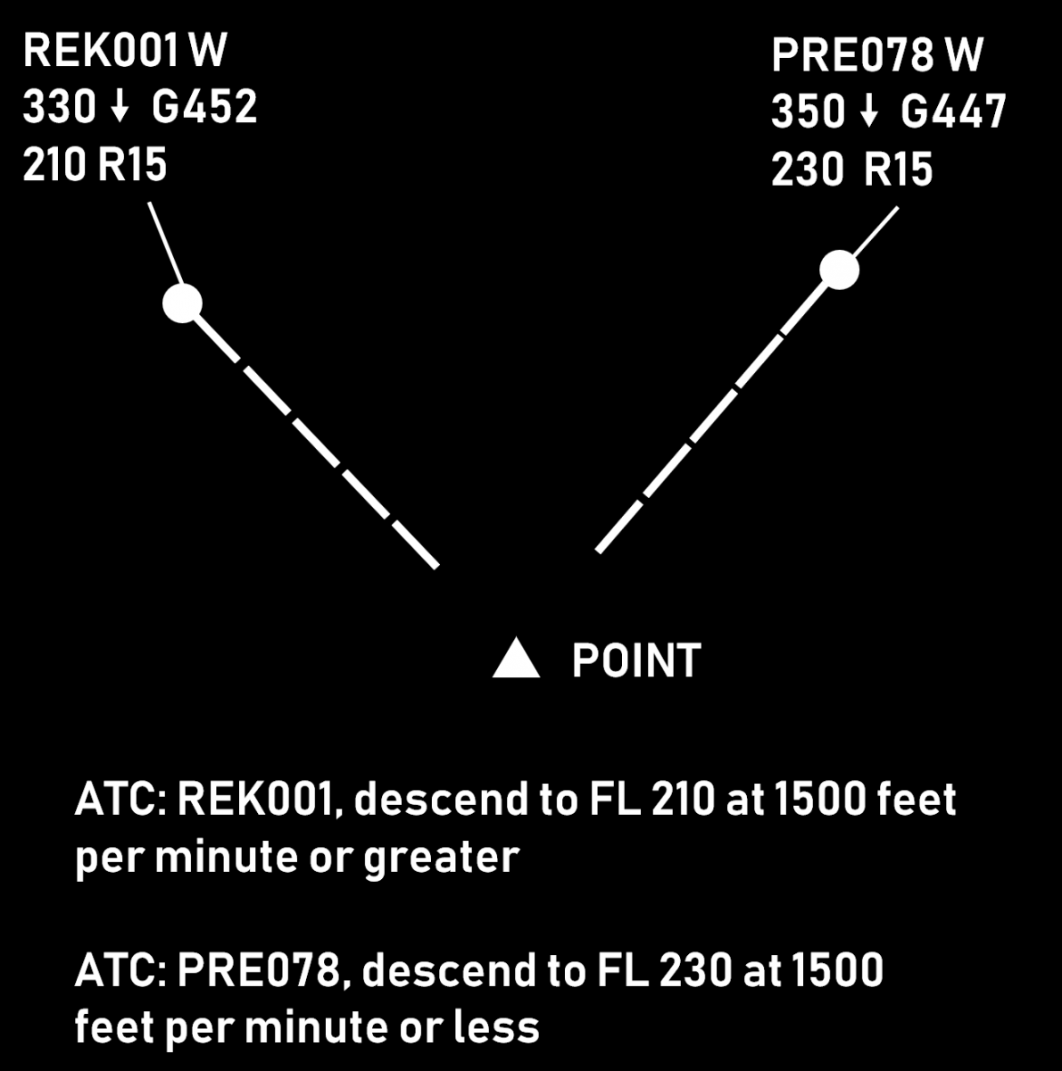 |
| Corrective action (e.g. when the unrestricted vertical speed is considered insufficient) | 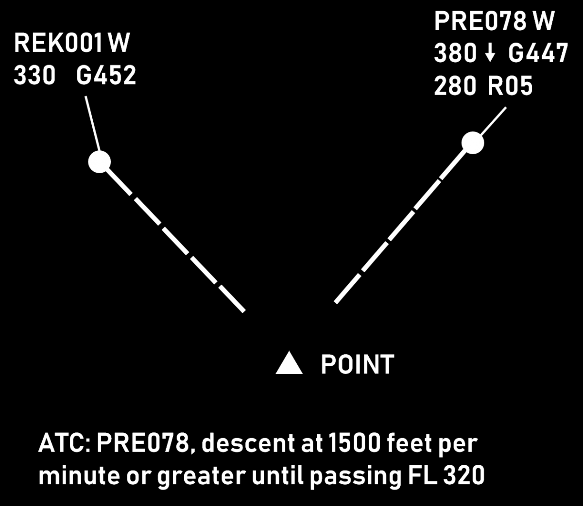 |
Benefits
When properly used, vertical speed control helps to achieve
- continuous climb/descend (fewer level offs), therefore better efficiency
- descents starting close to the top-of-descent
- timely accommodation of climb (mostly) and (sometimes) descent requests
- reduced workload due to reduced need for vectoring. A proper vertical speed ensures that horizontal separation will be preserved at least until vertical separation is achieved.
Associated Risks
- The margin for error is often reduced. This method relies mostly on maintaining vertical separation, which is much smaller than the horizontal one (e.g. 1000 ft as opposed to 5 NM). Therefore, any misunderstanding or non-compliance can easily result in loss of separation.
- Harder to monitor aircraft compliance (as opposed to e.g. vectoring). While the information for vertical speed is usually available, it may require some effort to present it. Furthermore, the interpretation of two (or more) numbers and the comparison of clearances versus performance takes more time than just having a look at the situational display (which is used to monitor horizontal separation).
- Aircraft may be unable to maintain the assigned rate of climb after certain level. If this happens, flight crew may or may not inform the controller.
- Wrong readback may easily ruin the plan (e.g. both aircraft descending with "or greater")
Things to Consider
- Rates of climb should be coordinated with the flight crew, especially:
- when approaching the cruising level
- when the climb is not desired by the flight crew
- when temperatures are high
- Some aircraft types are generally unable to maintain a high rate of climb (e.g. AIRBUS A-321, AIRBUS A-340-300)
- In order to mitigate the risks for crossing or opposite traffic situations, a safety buffer of 1 or 2 minutes should be used. This can be done by e.g.
- Issuing the clearance(s) a bit earlier
- Assigning vertical speeds that are a little higher (e.g. 1500 instead of 1000)
- High rates of descent are generally incompatible with low speeds. A combined instruction to reduce speed and increase the RoD should be coordinated with the flight crew.
- The aircraft needs time to achieve higher rates (2000 ft/min or higher). The transition period should be considered when calculating the necessary vertical speed.
- During the final 1000 ft, the vertical speed is usually 1000 ft/min or less. This is done to avoid level busts. It is therefore impractical to assign a rate of 2000 ft/min or greater if the aircraft is to climb or descend some 2000-3000 ft.
- The phrases "Expedite climb" and "Expedite descent", while being standard ICAO phraseology do not prescribe specific vertical speeds and should be used with caution. The general expectation in such case would be that:
- a climbing aircraft would climb at the highest rate possible (which may or may not be enough to achieve the desired result). It is therefore advisable that larger safety buffers are used or an alternative plan is ready for implementation.
- a descending aircraft would increase the rate of descent to at least 2000 ft/min. It is therefore advisable that this method is used for the first few thousand feet (e.g. for an aircraft at FL 390 "Descend FL 290, expedite passing FL 370 due crossing traffic")
- There should always be an alternative plan to accommodate for an aircraft being unable to continue climb with the desired rate.
Rules of Thumb
- Vertical speed of 2000 ft/min gives 10 FLs in 5 minutes
- Vertical speed of 2500 ft/min gives 10 FLs in 4 minutes
- Combined vertical speed of 4000 ft/min (e.g. RoD 2500 and RoC 1500) gives 20 FLs in 5 minutes
*Combined vertical speed is the sum of the vertical speeds of a climbing and a descending aircraft, e.g. if aircraft A is climbing at 1500 ft/min and aircraft B is descending at 2000 ft/min, then the combined vertical speed is 3500 ft/min.*
Level Change
While there are various reasons for a level change, this article focuses on the conflict solving aspect.
Description
Changing an aircraft's level is often the easiest way for a controller to solve a conflict, i.e. a situation where two (or more) aircraft are expected to be closer than the prescribed separation minima.
Advantages:
- Comparatively smaller intervention. The aircraft continues to fly using own navigation (as opposed to vectoring) and follows the planned route (as opposed to proceeding direct to some distant waypoint).
- Faster to achieve. Even when the aircraft is to climb or descend by 2000 ft, only 1000 are often enough to ensure separation with the conflicting aircraft (see section Opposite Levels for details). This means that the conflict is usually solved within less than a minute.
- Easier to monitor on a situation display. Wind can influence both aircraft speed and flight direction. Additionally, speed vectors can change direction due to specifics of the surveillance system (especially the presence or absence of a tracker). On the other hand, all modern ATS systems provide an indication for climb or descend (an arrow next to the aircraft level). This makes it much easier for a controller to monitor aircraft compliance.
- Less controller workload. Changing an aircraft's level normally requires one instruction and about a minute to achieve the required separation. By contrast, speed control usually requires prolonged monitoring (the required separation "builds up" gradually). Vectoring requires more instructions - at least one for the heading change and one for the return to own navigation but more can be necessary depending on the circumstances. This will also require a longer period of monitoring.
Disadvantages:
- The main disadvantage of a level change is that aircraft normally fly at their optimal cruise levels. Therefore, any level change leads to reduced efficiency. This effect gets worse when increasing the difference between the desired and the cleared level.
- The use of temporary level change (i.e. the aircraft climbs/descends to a safe level to solve a crossing conflict and then returns to its cruising level) requires two vertical movements (one climb and one descend) which is also sub-optimal in terms of efficiency.
- There is an inherent risk of a blind spot, i.e. the controller may solve a medium term (e.g. 15 minutes ahead) conflict while at the same time create a new one with an aircraft just below or above the one being instructed to change level.
- When vertically split sectors are used, the level change may require coordination with an adjacent upper or lower sector which increases the workload for both controllers.
Climb Vs. Descent
After deciding to solve a conflict by a level change, the controller must choose between climb and descent. The former is generally preferred, as it leads to better flight efficiency. However, in some situations descent is the better (or the only) option, e.g.:
- The aircraft is unable to climb due to weight. Note that weight reduces as fuel is burnt so a higher level may be acceptable later. In this case the controller should take into account that the climb rate could be less than usual.
- The aircraft is approaching its top-of-descent. Instructing an aircraft to climb shortly before it would request descent is not very beneficial to flight efficiency and can increase controller workload (the higher the aircraft, the more potential for conflicts during the descent).
- Turbulence is reported at the higher level. Vectoring, direct route or speed control are generally preferable in this situation.
- The manoeuvre is to be performed quickly (e.g. due to a conflict being detected late). In this case, if a climb instruction is issued, it may be declined by the crew, thus losing precious time.
If the controller is in doubt as of which option is preferable (and if both are available), the controller may first ask the pilot (time and workload permitting). The fact that the range of available speeds is reduced at higher levels should also be considered. If the climb is to be combined with a speed restriction, this should be coordinated with the crew beforehand.
Opposite Levels
In many situations a level change would require the aircraft to climb or descend by 2000 feet (so that the new level is appropriate to the direction of the flight). However, sometimes it is better to use an opposite level, i.e. one that is only 1000 feet above/below. This is often a good solution in case of crossing conflicts, i.e. where the paths of the two aircraft only intersect at one point and the level change is expected to be temporary.
- The solution is better in terms of flight efficiency because the aircraft will fly as close as possible to the desired level and the need for vertical movement will be reduced
- The opposite level may happen to be within the own sector, therefore no coordination with an adjacent upper or lower sector would be necessary. This reduces the workload of both controllers and is especially useful when there are multiple, vertically-split sectors.
It should be noted, that a few risks exist with this solution:
- If there is a flight on an opposite track, the normally expected 1000 ft separation would not exist
- In case of radio communication failure, the aircraft may fly at an opposite level much longer than expected and the exact moment of returning to the previous level may not be easy to determine.
The picture below show a situation where the use of opposite level is preferable. The level change will be required for a few minutes only and there is no opposite traffic.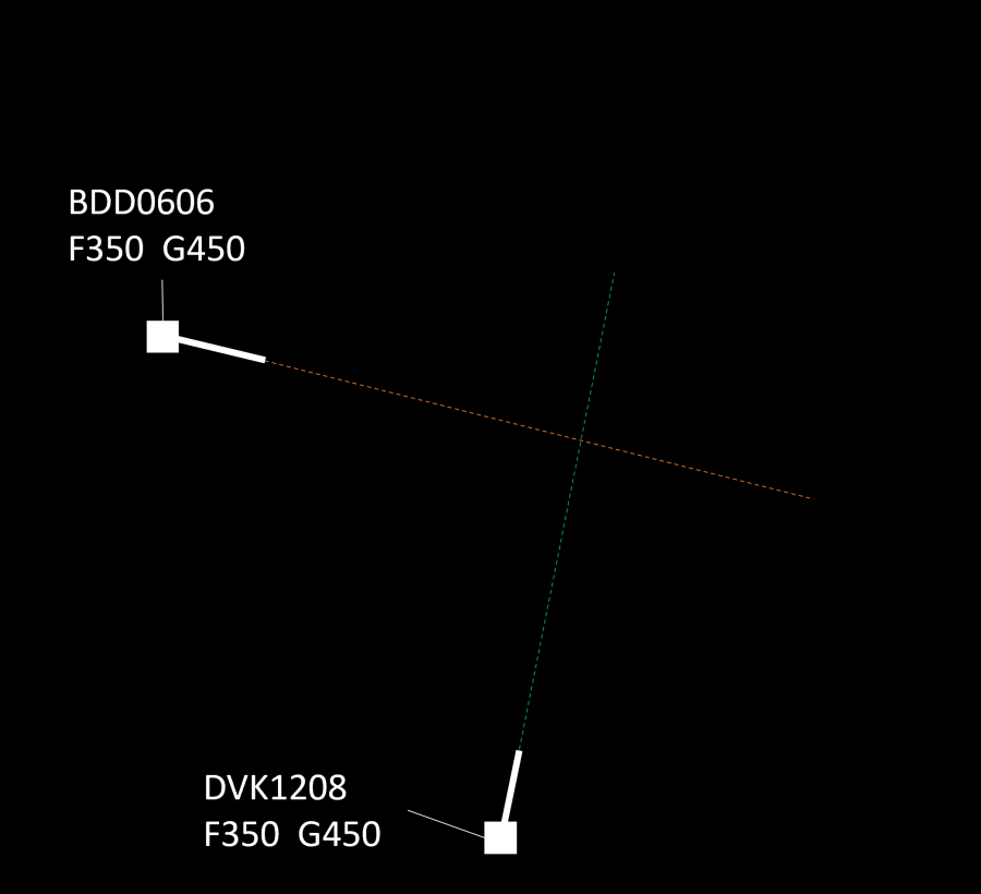
The picture below show a situation where the use of opposite level is not feasible because of opposite traffic. Therefore, a level change of 2000 ft is preferable.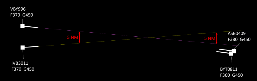
The use of opposite levels can sometimes be justified when the conflict is at the sector exit point. This solution, however, is subject to approval from the downstream controller. The feasibility of this option depends on the geometry of the conflict (are the aircraft diverging after the point of conflict) and on the traffic situation (are there aircraft that are flying at the same level on an opposite track).
Priorities
As a general rule, when two aircraft are at the same cruising level, the preceding aircraft would have priority, i.e. the succeeding aircraft will have to climb or descend. Other criteria may be specified in the manual of operations or other documents containing local procedures. In any case, the controller may deviate from these procedures based on the traffic situation. For example, if changing the level of the succeeding aircraft would create a new conflict (and thus, a new intervention would be necessary), the controller may opt to work with the preceding aircraft. Naturally, flights in distress, or those performing SAR operations, would have priority over other traffic. This includes obtaining (or maintaining) the desired level while a lower priority traffic (e.g. a commercial or general aviation flight) would have to change level. Other priorities may be specified in local procedures (e.g. flights with head of state on board).
Vertical Speed Considerations
Normally, vertical speed is not considered an issue in case of a level change solution to a conflict. This is because in most cases the instruction is issued well in advance (5-15 minutes before the potential separation breach) and the level change is 1000 or 2000 ft, which means that vertical separation will be achieved comfortably prior to losing the required horizontal spacing. Nevertheless, there are some situations where it might be necessary to ensure that the vertical speed will be sufficient. These include:
- There is a reason to believe that the aircraft will not (be able to) climb fast, e.g. a heavy long-haul flight in the initial cruise stage, the aircraft type is known to climb slower than others, the new level is near the ceiling, etc. While 1000 ft/min means that 1000 ft separation will be achieved in one minute, if the rate drops to 200 ft/min, the required time will be 5 minutes. In the scenario where 2000 ft level change is necessary (e.g. converging traffic at the sector exit point and an opposite traffic 1000 ft above), a 200-300 ft/min climb rate will result in a 7-10 minute climb.
- Sometimes, if a descent rate is not specified, the manoeuvre may start at rates in the range of 500 ft/min. In this case, a 2000 ft level change will require 4 minutes as opposed to only 1 or 2 if "normal" vertical speeds of 1000-2000 ft/min are used.
In such situations the controller should either:
- ensure the vertical speed will be sufficient (e.g. by specifying a desired rate of climb or descent), or
- issued the instruction early enough, or
- if the above are not possible, an use an alternative solution.
Source: www.skybrary.aero
Runway Change Guide
Runway changes can improve aerodrome efficiency but require careful coordination to ensure a smooth transition. The Tower controller is responsible for initiating a runway change, ensuring all affected units are informed, and managing the transition effectively. This guide outlines the procedures for a safe and efficient runway change.
Conditions for Runway Changes
A runway change may be necessary due to various factors, including but not limited to:
-
Weather Conditions:
- Significant wind shifts affecting operations.
- Consecutive missed approaches.
- Low Visibility Procedures (LVPs).
-
Operational Considerations:
- Runway equipment availability (e.g., ILS operational status).
- Optimised arrival sequencing for increased efficiency.
Initiating a Runway Change
When a runway change is deemed necessary, the Tower controller must coordinate the following with all relevant ATC units:
- Estimated time of runway change completion.
- Identification of the last departure using the current runway.
- Identification of the last arrival using the current runway
Tower declares the last arrival, but this must be confirmed by Approach (APP), as APP has the final say on arrivals.
The last departure and last arrival must be confirmed with Approach (APP) and Area (ACC) to ensure proper sequencing and spacing.
Aerodrome Procedures
Delivery (DEL)
- Aircraft previously cleared for departures on the old runway must be recleared for the appropriate SID.
- Once this is completed, all new aircraft should be issued clearances for the new runway as prescribed.
Ground (GND)
- Taxiing aircraft:
- The last departure should taxi to the current departure runway.
- All subsequent departures must be held until the last arrival has landed.
- Once the last arrival has landed, departures may taxi to the new runway.
- If Delivery was unable to reclear departures on the new SID, Ground is responsible for ensuring the correct departure clearance is issued.
Tower (TWR)
IFR Procedures
- Coordination with Approach:
- TWR must inform APP when the last arrival/departure is complete, signaling the start of the runway transition.
- The last arrival must be confirmed by APP, as APP has the final say on sequencing.
- The first departure on the new runway requires a release from APP before clearance is issued.
VFR Procedures
- Circuit traffic should be repositioned safely during the transition.
- VFR aircraft must be cleared for circuits on the new runway as soon as operationally feasible.
- Aircraft waiting for departure should be held in a safe area until the transition is complete.
Approach Procedures (APP)
- Once the last arrival has landed, APP must ensure all subsequent arrivals are sequenced for the new runway.
- If necessary, aircraft may be vectored for spacing before approach clearance to the new arrival runway.
- Caution is required: The last departure may not have departed yet, so careful sequencing must be maintained.
- APP must inform ACC when the runway change is complete.
Area Control Procedures (ACC)
- ACC should ensure arriving aircraft are cleared for the correct STAR leading to the new active runway.
- APP should notify ACC when the runway change is complete, allowing controllers to adjust area sequencing as necessary.
Managing Holding and Spacing During a Runway Change
- If traffic is heavy, Approach may identify a gap in arrivals where the runway change can be executed smoothly.
- The last arrivals on the old runway should land close together to minimize disruption.
- If necessary, short-term holding or vectoring may be used to space aircraft correctly before sequencing them to the new runway.
- Coordination between all ATC positions is critical to ensure a smooth transition.
Summary of Key Runway Change Steps
- Runway change is initiated by the Tower controller based on weather and operational factors.
- Tower coordinates with APP and ACC to determine the last departure and last arrival
- Delivery reclears affected departures and issues new runway clearances.
- Ground ensures proper taxi sequencing, holding aircraft as needed.
- Tower coordinates with Approach and obtains release for the first new departure.
- Approach vectors and sequences arrivals for the new runway while monitoring departure status.
- ACC clears aircraft for the appropriate STAR and coordinates with APP.
- APP informs ACC when the runway change is complete to resume normal operations.
Additional Best Practices for Runway Changes
- Advance planning is key—controllers should anticipate spacing issues before initiating the change.
- Clear communication between all controllers ensures a smooth transition.
- Time the first arrival for the new runway so that it reaches final approach shortly after the last arrival on the old runway has landed.
- Do not rush departures—ensure proper sequencing to avoid conflicts.
- Use holding or vectoring sparingly—only if needed to manage sequencing effectively.
Emergencies
An emergency is any situation that poses an immediate risk to an aircraft or its occupants. ATC must provide immediate assistance, unrestricted airspace, and minimal interference from other traffic.
Emergency Declarations
Pilots use the following standard phrases to declare emergencies:
- MAYDAY, MAYDAY, MAYDAY – Distress Call (Immediate assistance required)
- PAN-PAN, PAN-PAN, PAN-PAN – Urgency Call (Serious issue, but not immediate danger)
If unable to communicate verbally, pilots may squawk 7700 and attempt to contact ATC on 121.5 MHz.
Types of Emergency Landings
Forced Landing
A landing is required due to technical failures making continued flight impossible. Landing as soon as possible is the priority.
Common Causes:
- Engine failure or flameout
- Hydraulic or fuel leaks
- Structural damage
Precautionary Landing
A planned landing due to a developing issue that could worsen if the flight continues. These are usually done for safety reasons rather than immediate danger.
Common Causes:
- Landing gear problems (e.g., stuck gear, wheel punctures)
- Medical emergency onboard
Ditching
A forced landing on water, typically due to complete power loss over the ocean or a large body of water.
Common Causes:
- Total engine failure over water
- Fuel exhaustion
Emergency Classifications
Local Standby
The aircraft has a suspected issue that does not prevent a normal landing, but ATC treats it as an emergency.
Common Situations:
- Engine vibrations or failure of one engine in multi-engine aircraft
- Hydraulic issues affecting flaps or brakes
- Landing gear steering failure
- Smoke or odor in the cockpit
- Minor structural damage (e.g., bird strike)
Full Emergency
A serious emergency requiring immediate priority handling due to the risk of an accident.
Common Situations:
- Onboard fire (engine or cabin)
- Landing gear failure
- Flight control failure
- Cabin depressurization
Aircraft Accident
An aircraft accident occurs when an aircraft crashes on or near the airport. Immediate coordination with emergency services is required.
Handling Emergencies as ATC
Key Responsibilities:
- Acknowledge the emergency and confirm the details.
- Separate the emergency aircraft from all other traffic.
- Ensure silence on frequency if necessary.
- Inform and coordinate with relevant ATC units.
- Provide support by offering direct routing, weather updates, etc.
- Give time for pilots to manage the emergency.
The ASSISTED Memory Aid
ATC can use the ASSISTED checklist for structured emergency handling:
- Acknowledge – Confirm the emergency and understand the situation.
- Separate – Establish and maintain safe separation.
- Silence – Limit unnecessary radio transmissions.
- Inform – Notify relevant sectors (e.g., Approach, ACC, Tower).
- Support – Provide assistance (e.g., vectors, direct routing, alternate airports).
- Time – Allow the flight crew to focus on handling the emergency.
- Else, Disconnect – If the emergency disrupts ATC services, the pilot may be instructed to cancel the emergency or disconnect.
VATSIM Emergency Policy
Emergencies on VATSIM are subject to network rules:
- A pilot may only declare an emergency while under ATC service.
- ATC may request a pilot to terminate the emergency at any time.
- If a pilot refuses, they must disconnect.
- Hijackings (squawk 7500) and unlawful acts are strictly prohibited.
- If a pilot refuses to comply, .wallop for a Supervisor.
Emergency Handling by ATC Position
Tower Controller Responsibilities
- Acknowledge the emergency and instruct the pilot to squawk 7700 if necessary.
- Guide the aircraft back for landing (either visual approach or via ATC instructions).
- Coordinate with Approach and ensure they are aware of the emergency.
- Hold or divert other traffic:
- Stop all departures and arrivals.
- Instruct aircraft on the ground or final approach to hold position or go around.
- Keep runways clear for the emergency aircraft.
- Ensure smooth handoff to Approach if required.
Approach Controller Responsibilities
- Provide vectors to the nearest suitable runway.
- Delay or reroute other arrivals if needed.
- Use speed, altitude, or holding instructions to create space.
- Offer a visual or ILS approach depending on weather.
- Coordinate with Tower for priority landing.
Area Control (ACC) Responsibilities
- Direct the aircraft toward the nearest suitable airport.
- Coordinate with Approach and Tower.
- Use altitude or vectoring to ensure safe descent.
- Inform adjacent controllers if necessary.
Emergency Communication Procedures
An emergency call should include:
- Station being called (e.g., "Center, Mayday, Mayday, Mayday")
- Aircraft callsign
- Nature of emergency
- Intentions
- Position, altitude, heading, speed
- Fuel endurance and persons onboard (if relevant)
Example:
Mayday, Mayday, Mayday
Alpha 456, experiencing engine failure.
Request immediate return to airport.
Currently at FL120, heading 270, speed 280 knots.
Fuel endurance: 2 hours, 156 passengers onboard.
Emergency Operations at Multi-Runway Airports
- If multiple runways are available, non-emergency traffic may be moved to a secondary runway.
- This ensures the emergency aircraft has unrestricted access to the preferred runway.
- Delays should be minimized for other traffic while prioritizing the emergency.
Emergency Separation
If, during an emergency situation, it is not possible to ensure that the applicable horizontal separation can be maintained, emergency separation of half the applicable vertical separation minimum may be used. This means that a 1000 ft vertical separation minimum may be reduced to 500 ft and 2000 ft vertical separation minimum may be reduced to 1000 ft. All flight crews concerned must be advised if emergency separation is used.
Identification
Aircraft identification is a fundamental task in air traffic control, ensuring accurate tracking, communication, and coordination between controllers and pilots. Before issuing any ATC clearance in a Surveillance Services environment, an aircraft must be positively identified.
Methods of Identification
Aircraft can be identified using various methods:
- Unique Call Signs – Each aircraft has a unique identifier associated with its flight plan.
- Transponder Codes (SSR) – Squawk codes assigned by ATC for tracking and separation.
- Aircraft Type & Registration – Helps verify aircraft identity, especially in mixed traffic environments.
- ADS-B Data – Automatic Dependent Surveillance–Broadcast, providing real-time aircraft information.
If a pilot selects an incorrect SSR code or transponder mode, ATC must instruct them to correct it.
Radar Identification
Surveillance radar systems provide position, altitude, and speed data, allowing controllers to track and correlate aircraft targets accurately. Radar identification is required before providing ATC services.
When an aircraft leaves radar coverage or enters uncontrolled airspace, controllers must terminate radar service and inform the pilot accordingly.
Level Verification
- Controllers must verify the displayed level information at least once on initial contact.
- The tolerance for verifying accuracy:
- ±200 FT in RVSM airspace
- ±300 FT in non-RVSM airspace
If the displayed altitude exceeds tolerance values:
✔ Ask the pilot to confirm the correct altimeter setting (QNH)
✔ If necessary, instruct the pilot to disable Mode C altitude reporting
Unlike tower controllers, who can visually observe aircraft, radar controllers rely entirely on surveillance data from various systems.
Primary Surveillance Radar (PSR)
How PSR Works
- PSR transmits electromagnetic waves and displays reflections on the radar screen.
- Each reflection represents an aircraft, but PSR does not transmit aircraft identity information.
- Identification must be performed manually using position correlation or maneuver-based methods.
Methods of Identifying Aircraft Using PSR
- Position Reports – Correlating a radar target with a pilot's position report (distance & bearing from a known point).
- Departing Aircraft – Assigning a radar target to an aircraft departing within 1 NM of the runway end.
- Turn Method – Instructing an aircraft to turn by 30° or more and observing the corresponding radar movement.
- Transfer of Identification – Another controller transfers a positively identified aircraft to your control.
Secondary Surveillance Radar (SSR)
How SSR Works
- Unlike PSR, SSR actively interrogates aircraft transponders, which reply with encoded data.
- Provides enhanced aircraft identification, reducing workload and increasing accuracy.
SSR Interrogation Modes
| Mode | Transmitted Data |
|---|---|
| A | 4-digit squawk code |
| C | Pressure altitude |
| S | Callsign, 24-bit aircraft address, selected altitude, speed, etc. |
Modes A and C are often combined as Mode 3A/C.
Methods of Identifying Aircraft Using SSR
✔ Recognition of aircraft callsign in an SSR label
✔ Recognition of an assigned discrete squawk code
✔ Observation of a pilot-acknowledged squawk IDENT activation
✔ Transfer of identification from another controller
The most common method of identification on VATSIM is recognizing the aircraft ID (callsign) in an SSR label. If a pilot is unable to activate their transponder, they can be identified using PSR methods.
Reading and Deviations of Transponder Values
While transponder deviations are less relevant in a simulated environment than in real life, controllers should still monitor transponder readouts for accuracy.
- A flight level is considered "reached," "maintained," or "left" based on the transponder reading.
- A 200-foot tolerance is generally applied on VATSIM.
- Any deviation beyond tolerance should be addressed with the pilot.
Pilots should be reminded to check their QNH settings if an altitude discrepancy is detected.
SSR & ADS-B in ATC Operations
SSR (Secondary Surveillance Radar) vs. ADS-B
SSR and ADS-B (Automatic Dependent Surveillance–Broadcast) are complementary technologies enhancing ATC surveillance:
| Technology | Function |
|---|---|
| SSR | Interrogates aircraft transponders to receive replies |
| ADS-B | Aircraft broadcasts its own position and data automatically |
Transponder Use in Ground Operations
- Before takeoff: The transponder should be turned on before departure.
- At airports with ground movement radar (SMGCS): The correct squawk code should be set before taxiing.
For more details on Surface Movement Guidance and Control Systems (SMGCS), refer to Skybrary.
Controller Responsibilities in Identification
Before Providing ATC Services
✔ Aircraft must be positively identified.
✔ Identification must be confirmed before issuing clearances.
✔ Inform the pilot of radar identification unless the previous sector already identified them.
If Transponder Issues Occur
✔ Instruct the pilot to check transponder settings.
✔ If Mode C data is unreliable, request them to disable altitude reporting.
Loss of Radar Contact
✔ If an aircraft leaves radar coverage, radar service must be terminated and the pilot must be informed.
✔ Procedural separation may be required if radar service is lost.
Phraseology
Introduction
Effective communication between pilots and air traffic controllers (ATC) is essential for flight safety and efficiency. Standardized phraseology ensures clarity, uniformity, and minimizes ambiguity in radiotelephony (RTF) communication.
The phraseology outlined here is based on ICAO Doc 4444, 16th edition (Nov 2016) and must be used in conjunction with proper call signs.
What is Phraseology?
Phraseology refers to the structured communication used between pilots and ATC. It ensures clear and precise transmissions to reduce misunderstandings.
- Standard phraseology applies to routine and emergency communications.
- When standard phrases do not cover a situation, pilots and controllers should use plain language that is clear, concise, and direct.
- Pilots must read back all clearances and instructions they receive from ATC, except in emergency situations or in cases of radio failure.
Basic Rules of Communication
- ATC must start all transmissions with the aircraft’s call sign.
- Pilots should end their readback with their call sign.
- When contacting ATC for the first time, a pilot should state both the ATC unit and their own call sign.
- Some abbreviations, such as ILS, QNH, and RVR, may be spoken as individual letters rather than using the full phonetic alphabet.
Omitted Words in Transmissions
To keep transmissions concise, the following words may be omitted if no confusion arises:
- "Surface" (in relation to wind direction and speed).
- "Degrees" (when giving radar headings).
- "Visibility," "Clouds," and "Height" (in meteorological reports).
- "Hectopascal" (when providing pressure settings).
Use of Conditional Instructions
Conditional instructions (e.g., "Behind landing aircraft, line up and wait") must follow a strict format to avoid confusion.
Format for Conditional Instructions:
- Identification – Aircraft receiving the instruction.
- Condition – The reference traffic or event (e.g., "Behind the landing Airbus A320").
- Clearance – The specific instruction given (e.g., "Line up and wait").
Example:
📡 ATC: "SAS947, behind landing DC9, line up and wait Runway 12."
🛩 Pilot: "Behind landing DC9, line up and wait Runway 12, SAS947."
Important: Conditional phrases must not be used for runway movements unless the controller and pilot have a clear visual of the aircraft or vehicle in question.
Transmitting Techniques
To ensure clear and understandable communication, ATC and pilots should:
- Listen before transmitting to avoid interference.
- Use a normal tone and speak clearly and distinctly.
- Maintain a steady speaking volume throughout the transmission.
- Pause slightly before and after numbers for better comprehension.
- Avoid hesitation sounds like "er" or "um."
- Keep a consistent distance from the microphone for clear audio.
- Depress the transmit button fully before speaking and release it only after completing the message.
Readback Procedures
Pilots must read back all safety-critical clearances and instructions. This ensures that ATC clearances are received correctly and executed as intended.
Readback is mandatory for:
- ATC route clearances.
- Runway instructions, including:
- Entering, landing on, taking off from, or holding short of a runway.
- Crossing or backtracking on a runway.
- Runway-in-use information.
- Altimeter settings.
- SSR codes (Squawk assignments).
- Level, heading, and speed instructions.
- Transition level assignments.
Example Readbacks:
📡 ATC: "DEHBA, taxi to holding point Runway 01."
🛩 Pilot: "Taxi to holding point Runway 01, DEHBA."
📡 ATC: "DEHBA, squawk 4525."
🛩 Pilot: "Squawk 4525, DEHBA."
Additional Guidelines for Effective Communication
- The word "IMMEDIATELY" should only be used when immediate action is required for safety reasons.
- Avoid unnecessary courtesies like "please" or "thank you" in radio transmissions.
- Do not use redundant words such as "this is," "over," or similar terms unless needed for clarity.
General
Description of Level
ATC instructions or clearances may contain a specific level to comply with.
Levels are transmitted using the following formats:
- FLIGHT LEVEL (Number)
- (Number) METRES
- (Number) FEET
This (level) description will be used throughout this document.
Examples:
- FLIGHT LEVEL 90
- FLIGHT LEVEL 340
- 300 METRES
- 8500 FEET
Speed Control
ATC Speed Instructions:
- REPORT SPEED
- MAINTAIN (Number) KILOMETRES PER HOUR (or KNOTS) [OR GREATER (or OR LESS)] [UNTIL (Significant Point)]
- DO NOT EXCEED (Number) KILOMETRES PER HOUR (or KNOTS)
- MAINTAIN PRESENT SPEED
- INCREASE (or REDUCE) SPEED TO (Number) KILOMETRES PER HOUR (or KNOTS) [OR GREATER (or OR LESS)]
- INCREASE (or REDUCE) SPEED BY (Number) KILOMETRES PER HOUR (or KNOTS)
- RESUME NORMAL SPEED
- REDUCE TO MINIMUM APPROACH SPEED
- REDUCE TO MINIMUM CLEAN SPEED
- RESUME PUBLISHED SPEED
Canceling Speed Restrictions:
- NO [ATC] SPEED RESTRICTIONS
Pilot Response to Speed Queries:
- SPEED (Number) KILOMETRES PER HOUR (or KNOTS)
Level Changes, Reports, and Rate
Climb Instructions:
- CLIMB TO (Level)
- CLIMB TO AND MAINTAIN BLOCK (Level) TO (Level)
- CLIMB TO REACH (Level) AT (Time or Significant Point)
- CLIMB TO (Level), REPORT LEAVING/REACHING/PASSING (Level)
- CLIMB AT (Number) FEET PER MINUTE [OR GREATER/LESS]
- CLIMB AT (Number) METRES PER SECOND [OR GREATER/LESS]
- REPORT STARTING ACCELERATION (or DECELERATION). (only for supersonic jets)
Descent Instructions:
- DESCEND TO (Level)
- DESCEND TO AND MAINTAIN BLOCK (Level) TO (Level)
- DESCEND TO REACH (Level) AT (or BY) (Time or Significant Point)
- DESCEND REPORT LEAVING (or REACHING, or PASSING) (Level)
- DESCEND AT (Number) FEET PER MINUTE [OR GREATER/LESS]
- DESCEND AT (Number) METRES PER SECOND [OR GREATER/LESS]
- REPORT STARTING ACCELERATION/DECELERATION. (only for supersonic jets)
Climb and Descent Adjustments:
- MAINTAIN AT LEAST (Number) METRES (or FEET) ABOVE (or BELOW) (Aircraft Call Sign)
- STOP CLIMB (or DESCENT) AT (Level)
- CONTINUE CLIMB (or DESCENT) TO (Level)
- EXPEDITE CLIMB (or DESCENT) [UNTIL PASSING (Level)]
- WHEN READY CLIMB (or DESCEND) TO (Level)
- EXPECT CLIMB (or DESCENT) AT (Time or Significant Point)
Adding Restrictions to Climb/Descent:
- CROSS (Significant Point) AT (or ABOVE, or BELOW) (Level)
- CROSS (Significant Point) AT (Time) OR LATER (or BEFORE) AT (Level)
- CRUISE CLIMB BETWEEN (Levels) (or ABOVE (Level))
- CROSS (Distance) MILES, (GNSS or DME) [(Direction)] OF (Name of DME Station) OR (Distance) [(Direction)] OF (Significant Point) AT (or ABOVE or BELOW) (Level)
Altimeter Settings and Level Confirmation:
- CHECK ALTIMETER SETTING AND CONFIRM (Level)
- CONFIRM (Level)
Pilot Requests for Flight Level Change:
- REQUEST LEVEL (or FLIGHT LEVEL or ALTITUDE)
- REQUEST DESCENT AT (Time)
ATC Instructions for Immediate or Conditional Actions:
- IMMEDIATELY
- AFTER PASSING (Significant Point)
- AT (Time or Significant Point)
ATC Instruction for Action When Convenient:
- WHEN READY (Instruction)
ATC Instruction for Own Separation in VMC:
- MAINTAIN OWN SEPARATION AND VMC [FROM (Level)] [TO (Level)]
- MAINTAIN OWN SEPARATION AND VMC ABOVE (or BELOW, or TO) (Level)
Handling Compliance Uncertainty:
- IF UNABLE (Alternative Instructions) AND ADVISE
Pilot Response When Unable to Comply:
- UNABLE
TCAS Alert Management
Pilot and ATC Exchange During TCAS RA (Resolution Advisory):
- Pilot: "TCAS RA."
- ATC: "ROGER."
After Resolving the TCAS RA and Returning to ATC Clearance:
- Pilot: "CLEAR OF CONFLICT, RETURNING TO (Assigned Clearance)."
- ATC: "ROGER (or Alternative Instructions)."
After Resolving TCAS RA and Resuming Assigned ATC Clearance:
- Pilot: "CLEAR OF CONFLICT, (Assigned Clearance) RESUMED."
- ATC: "ROGER (or Alternative Instructions)."
If ATC Issues a Contradictory Instruction During an RA Event:
- Pilot: "UNABLE, TCAS RA."
- ATC: "ROGER."
Maneuver Instructions
ATC Instructions for Specific Maneuvers:
- MAKE A THREE SIXTY TURN LEFT (or RIGHT) [Reason]
- ORBIT LEFT (or RIGHT) [Reason]
- MAKE ALL TURNS RATE ONE (or RATE HALF, or (Number) DEGREES PER SECOND) START AND STOP ALL TURNS ON THE COMMAND "NOW"
- TURN LEFT (or RIGHT) NOW
- STOP TURN NOW
Reasons for Vectoring or Maneuvers:
- DUE TRAFFIC
- FOR SPACING
- FOR DELAY
- FOR DOWNWIND (or BASE, or FINAL)
Transfer of Control and Frequency Changes
ATC Transfer Instructions:
- CONTACT (Unit Call Sign) (Frequency) [NOW]
- WHEN READY CONTACT (Unit Call Sign) (Frequency)
- REMAIN THIS FREQUENCY
Pilot Request for Frequency Change:
- REQUEST CHANGE TO (Frequency)
- ATC: "FREQUENCY CHANGE APPROVED."
ATC Instruction to Stand By:
- STAND BY FOR (Unit Call Sign) (Frequency)
ATC Instruction to Monitor a Frequency:
- MONITOR (Unit Call Sign) (Frequency)
- Example: "MONITOR UNICOM 122.8."
Entering Airspace Clearance
ATC Instructions for Entering/Leaving Controlled Airspace:
- ENTER CONTROLLED AIRSPACE (or CONTROL ZONE) [VIA (Significant Point or Route)] AT (Level) [AT (Time)]
- LEAVE CONTROLLED AIRSPACE (or CONTROL ZONE) [VIA (Significant Point or Route)] AT (Level) (or CLIMBING, or DESCENDING)
ATC Instruction for Specific Route with Restrictions:
- JOIN (Specify) AT (Significant Point) AT (Level) [AT (Time)]
Termination of Radar Service
ATC Instructions for Ending Radar Services:
- RADAR SERVICE (or IDENTIFICATION) TERMINATED [DUE (Reason)] (Instructions)
- WILL SHORTLY LOSE IDENTIFICATION (Appropriate Instructions or Information)
- IDENTIFICATION LOST [Reasons] (Instructions)
Change of Call Sign
When an ATC unit has two aircraft with similar call signs that could cause confusion, the controller may instruct one aircraft to change its call sign.
Example of Conflicting Call Signs:
- AFR145 and AFR945
ATC Instructions for Call Sign Change:
- CHANGE YOUR CALL SIGN TO (New Call Sign) [UNTIL FURTHER ADVISED]
- REVERT TO FLIGHT PLAN CALL SIGN (Call Sign) [AT (Significant Point)]
Traffic Information
ATC Instructions for Providing Traffic Information:
- TRAFFIC (Information)
- TRAFFIC (Number) O'CLOCK (Distance) (Direction of Flight) [Any Other Pertinent Information]
Additional Descriptors for Traffic Reports:
- UNKNOWN
- SLOW MOVING
- FAST MOVING
- CLOSING
- OPPOSITE (or SAME) DIRECTION
- OVERTAKING
- CROSSING LEFT TO RIGHT (or RIGHT TO LEFT)
- (Aircraft Type)
- (Level)
- CLIMBING (or DESCENDING)
ATC Notification for No Reported Traffic:
- NO REPORTED TRAFFIC
ATC Guidance for Avoiding Action:
- DO YOU WANT VECTORS?
Pilot Requests for Avoiding Action Vectors:
- REQUEST VECTORS
ATC Instructions for Immediate Avoidance:
- TURN LEFT (or RIGHT) IMMEDIATELY HEADING (Three Digits) TO AVOID [UNIDENTIFIED] TRAFFIC (Bearing by Clock-Reference and Distance)
- TURN LEFT (or RIGHT) (Number of Degrees) DEGREES IMMEDIATELY TO AVOID [UNIDENTIFIED] TRAFFIC AT (Bearing by Clock-Reference and Distance)
ATC Notification for No More Traffic Threats:
- CLEAR OF TRAFFIC [Appropriate Instructions]
Pilot Acknowledgement of Traffic Information:
- LOOKING OUT
- TRAFFIC IN SIGHT
- NEGATIVE CONTACT [Reasons]
- [ADDITIONAL] TRAFFIC (Direction) BOUND (Type of Aircraft) (Level) ESTIMATED (or OVER) (Significant Point) AT (Time)
- TRAFFIC IS (Classification) UNMANNED FREE BALLOON(S) WAS [or ESTIMATED] OVER (Place) AT (Time) REPORTED (Level(s)) [or LEVEL UNKNOWN] MOVING (Direction) (Other Pertinent Information, If Any)
Meteorological Conditions
ATC Wind Information:
- [SURFACE] WIND (Number) DEGREES (Speed) (Units)
- WIND AT (Level) (Number) DEGREES (Number) KILOMETRES PER HOUR (or KNOTS)
- Note: Wind is always expressed by giving the mean direction and speed and any significant variations thereof.
ATC Runway Visual Range (RVR) Information:
- RUNWAY VISUAL RANGE (or RVR) [RUNWAY (Number)] (Distance) (Units)
- RUNWAY VISUAL RANGE (or RVR) RUNWAY (Number) NOT AVAILABLE (or NOT REPORTED)
Multiple RVR Observations:
- RUNWAY VISUAL RANGE (or RVR) [RUNWAY (Number)] (First Position) (Distance) (Units), (Second Position) (Distance) (Units), (Third Position) (Distance) (Units)
- Note 1: Multiple RVR observations represent the touchdown zone, midpoint, and roll-out/stop end zone, respectively.
- Note 2: When reports for all three locations are given, the location names may be omitted if passed in this order.
ATC RVR Information When One Position is Unavailable:
- RUNWAY VISUAL RANGE (or RVR) [RUNWAY (Number)] (First Position) (Distance) (Units), (Second Position) NOT AVAILABLE, (Third Position) (Distance) (Units)
Other Weather Information Provided by ATC:
- PRESENT WEATHER (Details)
- CLOUD (Amount, [(Type)] and Height of Base) (Units)
- SKY CLEAR
- CAVOK (Pronounced CAV-O-KAY)
- TEMPERATURE [MINUS] (Number) (and/or DEWPOINT [MINUS] (Number))
- QNH (Number) [Units]
- QFE (Number) [(Units)]
- (Aircraft Type) REPORTED (Description) ICING (or TURBULENCE) [IN CLOUD] (Area) (Time)
- REPORT FLIGHT CONDITIONS
Position Reporting
ATC Instructions for Position Reporting:
- REPORT PASSING (Significant Point)
- NEXT REPORT AT (Significant Point)
ATC Instruction to Omit Position Reports Until a Certain Point:
- OMIT POSITION REPORTS [UNTIL (Specify)]
ATC Instruction to Resume Position Reporting:
- RESUME POSITION REPORTING
ATC Instruction to Request a Report at a Specific Location or Distance:
- REPORT (Distance) MILES (GNSS or DME) FROM (Name of DME Station) (or Significant Point)
ATC Instruction to Report Position Using VOR Radial:
- REPORT PASSING (Three Digits) RADIAL (Name of VOR) VOR
ATC Instruction to Request a Report of Present Position:
- REPORT (GNSS or DME) DISTANCE FROM (Significant Point) or (Name of DME Station)
Typical Pilot Position Report:
- (Distance) MILES (GNSS or DME) FROM (Name of DME Station) (or Significant Point)
- (Coordinates North/South) and (Coordinates East/West)
Aerodrome Information
ATC Instructions Regarding Aerodrome Conditions:
- [(Location)] RUNWAY SURFACE CONDITION RUNWAY (Number) (Condition)
- [(Location)] RUNWAY SURFACE CONDITION RUNWAY (Number) NOT CURRENT
- LANDING SURFACE (Condition)
- CAUTION CONSTRUCTION WORK (Location)
- CAUTION (Specify Reasons) RIGHT (or LEFT), (or BOTH SIDES) OF RUNWAY [Number]
- CAUTION WORK IN PROGRESS (or OBSTRUCTION) (Position and Any Necessary Advice)
Runway Surface Reports and Braking Action:
- RUNWAY REPORT AT (Observation Time) RUNWAY (Number) (Type of Precipitant) UP TO (Depth of Deposit) MILLIMETRES. ESTIMATED SURFACE FRICTION GOOD (or MEDIUM TO GOOD, or MEDIUM, or MEDIUM TO POOR, or POOR)
- BRAKING ACTION REPORTED BY (Aircraft Type) AT (Time) GOOD (or MEDIUM TO GOOD, or MEDIUM, or MEDIUM TO POOR, or POOR)
Additional Runway or Taxiway Conditions:
- RUNWAY (or TAXIWAY) (Number) WET [or STANDING WATER, or SNOW REMOVED (Length and Width as Applicable), or TREATED, or COVERED WITH PATCHES OF DRY SNOW (or WET SNOW, or COMPACTED SNOW, or SLUSH, or FROZEN SLUSH, or ICE, or WET ICE, or ICE UNDERNEATH, or ICE AND SNOW, or SNOWDRIFTS, or FROZEN RUTS AND RIDGES)]
Additional Observations:
- TOWER OBSERVES (Weather Information)
- PILOT REPORTS (Weather Information)
Issuance of Clearance
ATC Clearance Given to the Pilot:
- (Aircraft Call Sign) CLEARED TO (or FOR) (Clearance)
- Example: N52515, Runway 10, cleared to land.
- Example: N11444, Runway 33R, cleared for take-off.
Reporting ATC Clearance Given by Another ATC Unit:
- (Name of Unit) CLEARS (Aircraft Call Sign) TO (Clearance)
Modified Clearance Given by ATC:
- RECLEARED (Amended Clearance Details) [REST OF CLEARANCE UNCHANGED]
- RECLEARED (Amended Route Portion) TO (Significant Point of Original Route) [REST OF CLEARANCE UNCHANGED]
Types of Clearance:
- Departure Clearance
- Arrival Clearance
- Crossing Zone Clearance
- Flight Plan Change Clearance
Indicating Route and Clearance Limit:
- FROM (Location) TO (Location)
- TO (Location)
- TO (Location), DIRECT
- TO (Location), VIA (Route and/or Significant Points)
- TO (Location), FLIGHT PLANNED ROUTE
- TO (Location), VIA (Distance) DME ARC (Direction) OF (Name of DME Station)
When Clearance Cannot Be Issued or Followed:
- (Route) NOT AVAILABLE DUE (Reason) ALTERNATIVE(S) IS/ARE (Routes) ADVISE.
- CANNOT BE ISSUED
- UNABLE, TRAFFIC (Direction) BOUND (Type of Aircraft) (Level)
- ESTIMATED (or OVER) (Significant Point) AT (Time) CALL SIGN
- (Call Sign) ADVISE INTENTIONS.
Transponder Mode and Code
ATC Instructions to Change or Check the Transponder Mode and/or Code:
- RESET SQUAWK [(Mode)] (Code)
- CONFIRM SQUAWK (Code)
Pilot Readback for Transponder Instructions:
- RESETTING [(Mode)] (Code)
- SQUAWKING (Code)
ATC Instruction for Squawking IDENT Procedure:
- SQUAWK [(Code)] [AND] IDENT
ATC Request for Suspension of Transponder Operation (Standby Mode):
- SQUAWK STANDBY
ATC Request for Emergency Code (MAYDAY) Setting:
- SQUAWK MAYDAY [CODE SEVEN-SEVEN-ZERO-ZERO]
ATC Request for Transmission of Pressure Altitude:
- SQUAWK CHARLIE
- TRANSMIT ADS-B ALTITUDE
Aerodrome
Initial IFR Clearance Request
Every flight under Instrument Flight Rules (IFR) must receive an initial IFR clearance. This clearance approves the flight plan and allows the flight to proceed.
Clearances Shall Contain:
- Aircraft identification
- Clearance limit
- Designator of the assigned SID (if applicable)
- Cleared level(s)
- Allocated SSR code (squawk/transponder code)
- Any other necessary instructions or information not contained in the SID description (e.g., non-standard departure route, change of frequency instructions)
Example IFR Clearances:
- CLEARED TO (destination airfield) VIA (departure SID identifier) DEPARTURE, [RUNWAY (departure runway)], FLIGHT PLANNED ROUTE, CLIMB (initial level), SQUAWK (squawk number).
- CLEARED TO (destination airfield), FLIGHT PLANNED ROUTE, CLIMB (initial level), AFTER DEPARTURE (description of the clearance to follow - omnidirectional or non-standard clearance), SQUAWK (squawk number).
Example of a Vectored Departure:
Pilot Requests Permission to Start:
Starting Procedures
Example Requests:
- [Aircraft location] REQUEST START UP
- [Aircraft location] REQUEST START UP, INFORMATION (ATIS identification)
- START UP APPROVED
- START UP AT (time)
- EXPECT START UP AT (time)
- START UP AT OWN DISCRETION
- EXPECT DEPARTURE (time), START UP AT OWN DISCRETION
In some countries, starting procedures do not oblige the pilot to start engines immediately. It grants permission to initiate the complex starting process.
Pushback Procedures
Pilot Requests a Pushback:
- [Aircraft location] REQUEST PUSHBACK
- PUSHBACK APPROVED
- STAND BY
- PUSHBACK AT OWN DISCRETION
- EXPECT (number) MINUTES DELAY DUE TO (reason).
At some airports, pushback authorization must be obtained from the control tower.
Towing Procedure:
- REQUEST TOWING FROM (Aircraft location) TO (location)
- TOW APPROVED VIA (specific routing to be followed)
- HOLD POSITION
- STAND BY
Requesting Departure Information
Pilot Requests Departure Information (If No ATIS Broadcast Is Available or Information Is Outdated)
- REQUEST DEPARTURE INFORMATION
ATC Reply:
- RUNWAY (number), WIND (direction and speed) (units), QNH (or QFE) (number) [(units)], TEMPERATURE [MINUS] (number), [VISIBILITY (distance) (units) (or RUNWAY VISUAL RANGE (RVR) (distance) (units))], TIME (time)
Taxi Procedures
Pilot Requests Taxi to Assigned Runway (Given in Clearance)
- [Aircraft type] [wake turbulence category if "heavy"] [Aircraft location] REQUEST TAXI [intentions]
- [Aircraft type] [wake turbulence category if "heavy"] [Aircraft location] (flight rules) TO (destination aerodrome) REQUEST TAXI [intentions]
ATC Taxi Instructions:
- TAXI TO HOLDING POINT [number] [RUNWAY (number)] [HOLD SHORT OF RUNWAY (number) (or CROSS RUNWAY (number))] [TIME (time)]
- TAXI TO HOLDING POINT [number] [RUNWAY (number)] VIA (specific route) [HOLD SHORT OF RUNWAY (number) (or CROSS RUNWAY (number))] [TIME (time)]
- [Aircraft type] [wake turbulence category if "heavy"] REQUEST DETAILED TAXI INSTRUCTIONS
- TAXI TO HOLDING POINT [number] [RUNWAY (number)] VIA (specific route) [TIME (time)] [HOLD SHORT OF RUNWAY (number) (or CROSS RUNWAY (number))]
Other Taxi Instructions:
- TAKE (or TURN) FIRST (or SECOND) LEFT (or RIGHT)
- TAXI VIA (identification of taxiway)
- TAXI STRAIGHT AHEAD
- TAXI TO TERMINAL [STAND (number)]
- TAXI TO GENERAL AVIATION AREA
- TAXI TO (other location)
- TAXI VIA RUNWAY (number)
Helicopter Taxi Procedures
Pilot Requests Movement:
- REQUEST AIR-TAXIING FROM (or VIA) TO (location or routing as appropriate)
ATC Reply:
- AIR-TAXI TO (or VIA) (location or routing as appropriate) [CAUTION (dust, blowing snow, loose debris, taxiing light aircraft, personnel, etc.)]
- AIR-TAXI VIA (direct, as requested, or specified route) TO (location, heliport, operating or movement area, active or inactive runway). AVOID (aircraft or vehicles or personnel)
Runway Operations
Pilot Requests Backtracking:
- REQUEST BACKTRACK
- BACKTRACK APPROVED
- BACKTRACK RUNWAY (number)
ATC Instructions for Taxiing Aircraft with Traffic:
- TAXI WITH CAUTION
- GIVE WAY TO (description and position of other aircraft)
- GIVING WAY TO (traffic)
- TRAFFIC (or type of aircraft) IN SIGHT
- TAXI INTO HOLDING BAY
- FOLLOW (description of other aircraft or vehicle)
- VACATE RUNWAY
- EXPEDITE TAXI [(reason)]
- [CAUTION] TAXI SLOWER [reason]
- RUNWAY VACATED
- EXPEDITING
- SLOWING DOWN
Holding on the Ground
ATC Instructions:
- HOLD (direction) OF (position, runway number, etc.)
- HOLD POSITION
- HOLD (distance) FROM (position)
- HOLD SHORT OF (position)
Pilot Replies:
- HOLDING
- HOLDING SHORT
The procedure words "ROGER" and "WILCO" are not sufficient acknowledgements for HOLD, HOLD POSITION, or HOLD SHORT OF instructions. Pilots must explicitly respond with HOLDING or HOLDING SHORT as appropriate.
Crossing Runway
Pilot Requests a Runway Cross:
- REQUEST CROSS RUNWAY (number)
If the control tower cannot see the crossing aircraft (e.g., at night, in low visibility), the instruction must be accompanied by a request to report when the aircraft has vacated the runway.
ATC Replies:
- CROSS RUNWAY (number) [REPORT VACATED]
- EXPEDITE CROSSING RUNWAY (number) TRAFFIC (aircraft type) (distance) KILOMETRES (or MILES) FINAL
- TAXI TO HOLDING POINT [number] [RUNWAY (number)] VIA (specific route), [HOLD SHORT OF RUNWAY (number)] or [CROSS RUNWAY (number)]
Pilots must report "RUNWAY VACATED" when the entire aircraft has cleared the relevant runway-holding position.
Reporting Runway Vacation
Pilot Reports After Runway Vacated:
- RUNWAY VACATED
Preparation for Take-Off
ATC Checks If Pilot Is Ready for Departure:
- REPORT WHEN READY [FOR DEPARTURE]
- ARE YOU READY [FOR DEPARTURE]?
- ARE YOU READY FOR IMMEDIATE DEPARTURE?
Pilot Replies:
- READY
ATC Instructions to Line Up:
- LINE UP [AND WAIT]
- LINE UP RUNWAY (number)
- LINE UP. BE READY FOR IMMEDIATE DEPARTURE
-
LINE UP AND WAIT RUNWAY (number), INTERSECTION (name of intersection), (essential traffic information)
ATC Conditional Clearance:
- (Condition) LINE UP RUNWAY (number) (brief reiteration of the condition)
- (Condition) LINING UP RUNWAY (number) (brief reiteration of the condition)
Pilot Acknowledges Conditional Clearance:
- [THAT IS] CORRECT
- (NEGATIVE) [I SAY AGAIN] (Instruction as appropriate)
Pilot Requests Departure Instructions:
- REQUEST DEPARTURE INSTRUCTIONS
ATC Replies:
- AFTER DEPARTURE TURN RIGHT (or LEFT, or CLIMB) (instructions as appropriate)
Take-off Clearance
ATC Clearance for Take-off:
- RUNWAY (number) CLEARED FOR TAKE-OFF [REPORT AIRBORNE]
- (Traffic information) RUNWAY (number) CLEARED FOR TAKE-OFF
- TAKE OFF IMMEDIATELY OR VACATE RUNWAY
- TAKE OFF IMMEDIATELY OR HOLD SHORT OF RUNWAY
ATC Instructions When Take-off Clearance Is Not Complied With:
- HOLD POSITION, CANCEL TAKE-OFF I SAY AGAIN CANCEL TAKE-OFF (reason)
- HOLDING
ATC Instruction to Stop a Take-off After an Aircraft Has Started the Take-off Roll:
- STOP IMMEDIATELY [(repeat aircraft call sign) STOP IMMEDIATELY]
- STOPPING
ATC Clearance for Helicopter Take-off:
- CLEARED FOR TAKE-OFF [FROM (location)] (present position, taxiway, final approach and take-off area, runway and number)
After Take-off
Pilot Requests Turn After Departure (VFR):
- REQUEST RIGHT (or LEFT) TURN
ATC Replies:
- RIGHT (or LEFT) TURN APPROVED
- WILL ADVISE LATER FOR RIGHT (or LEFT) TURN
ATC Instruction to Report Airborne:
- REPORT AIRBORNE
- AIRBORNE (time)
The phraseology "Airborne" is used based on local regulations. Some airports require it, others reserve it for military use, and some forbid it entirely.
ATC Instructions with Level Constraints:
- AFTER PASSING (level), (instructions)
ATC Instructions on Heading or Track:
- CONTINUE RUNWAY HEADING (instructions)
- TRACK EXTENDED CENTRE LINE (instructions)
- CLIMB STRAIGHT AHEAD (instructions)
Entering the Aerodrome Traffic Circuit (VFR)
Pilot Requests Clearance to Enter the Zone for Landing:
- [Aircraft type] (position) (level) INFORMATION (ATIS identification) FOR LANDING
- [Aircraft type] (position) (level) FOR LANDING
ATC Replies:
- JOIN [(direction of circuit)] (position in circuit) (runway number) [SURFACE] WIND (direction and speed) (units)
- JOIN (position in circuit) [RUNWAY (number)] QNH (or QFE) (number) [(units)] [TRAFFIC (detail)]
- MAKE STRAIGHT-IN APPROACH, RUNWAY (number) [SURFACE] WIND (direction and speed) (units) [TEMPERATURE [MINUS] (number)] QNH (or QFE) (number) [(units)] [TRAFFIC (detail)]
Pilot Reports Position Inside the Circuit:
- (position in circuit, e.g., DOWNWIND/FINAL), RUNWAY (number)
ATC Instructions for Traffic Sequence:
- NUMBER (number) FOLLOW (aircraft type and position) [additional instructions if required]
Final Approach Instructions (VFR)
ATC Instructions:
- MAKE SHORT APPROACH RUNWAY (number)
- MAKE LONG APPROACH RUNWAY (number)
- REPORT FINAL (or LONG FINAL) RUNWAY (number)
- REPORT BASE RUNWAY (number)
- CONTINUE APPROACH [PREPARE FOR POSSIBLE GO AROUND]
- EXTEND DOWNWIND RUNWAY (number)
- FINAL RUNWAY (number)
The report "FINAL" is required when the aircraft is less than 7 km (4 NM) from touchdown.
The report "LONG FINAL" applies when an aircraft turns onto final at more than 7 km (4 NM) or when an aircraft on a straight-in approach is 15 km (8 NM) from touchdown.
Landing Clearance
ATC Issues Landing Clearance:
- RUNWAY (number) CLEARED TO LAND
- (Traffic information), RUNWAY (number) CLEARED TO LAND
In all landing clearances, the term "CLEARED" is mandatory. The phrase "RUNWAY" followed by the runway number is also required.
Special Landing Operations:
- CLEARED TOUCH AND GO
- MAKE A FULL STOP
Special Aerodrome Operations
Pilot Requests a Low Approach:
- REQUEST LOW APPROACH (reason)
- CLEARED LOW APPROACH [RUNWAY (number)] [(altitude restriction if required) (go-around instructions)]
Pilot Requests a Low Pass:
- REQUEST LOW PASS (reason)
- CLEARED LOW PASS APPROACH [RUNWAY (number)] [(altitude restriction if required) (go-around instructions)]
Pilot Requests a Straight-in or Circling Approach:
- REQUEST STRAIGHT-IN (or CIRCLING APPROACH, LEFT (or RIGHT) TURN TO (location))
- MAKE STRAIGHT-IN (or CIRCLING APPROACH, LEFT (or RIGHT) TURN TO (location, runway, taxiway, final approach and take-off area)) [ARRIVAL (or ARRIVAL ROUTE) (number, name, or code)]. [HOLD SHORT OF (active runway, extended runway centre line, other)].
Delaying VFR Aircraft
ATC Instructions to Delay Landing:
- CIRCLE THE AERODROME
- ORBIT (RIGHT, or LEFT) [FROM PRESENT POSITION]
- MAKE ANOTHER CIRCUIT
Missed Approach
ATC Instructs Aircraft to Go Around:
- GO AROUND
Pilot Replies:
- GOING AROUND
Special Aerodrome Operations
ATC Instruction for Visual Inspection of Landing Gear (During a Low Pass):
- LANDING GEAR APPEARS DOWN
- RIGHT (or LEFT, or NOSE) WHEEL APPEARS UP (or DOWN)
- WHEELS APPEAR UP
- RIGHT (or LEFT, or NOSE) WHEEL DOES NOT APPEAR UP (or DOWN)
ATC Instruction for Wake Turbulence and Jet Blast Warnings:
- CAUTION WAKE TURBULENCE [FROM ARRIVING (or DEPARTING) (type of aircraft)] [additional information as required]
- CAUTION JET BLAST
- CAUTION SLIPSTREAM
Runway Vacating and Post-Landing Communication
ATC Instructions After Landing:
- CONTACT GROUND (frequency)
- WHEN VACATED CONTACT GROUND (frequency)
- EXPEDITE VACATING
- TAKE (or TURN) FIRST (or SECOND, or CONVENIENT) LEFT (or RIGHT) AND CONTACT GROUND (frequency)
- YOUR STAND (or GATE) (designation)
Helicopter Post-Landing Instructions:
- AIR-TAXI TO HELICOPTER STAND (or) HELICOPTER PARKING POSITION (area)
- AIR-TAXI TO (or VIA) (location or routing as appropriate) [CAUTION (dust, blowing snow, loose debris, taxiing light aircraft, personnel, etc.)]
- AIR-TAXI VIA (direct, as requested, or specified route) TO (location, heliport, operating or movement area, active or inactive runway). AVOID (aircraft or vehicles or personnel)
Approach
Departure Instructions
ATC Departure Instructions:
- [AFTER DEPARTURE] TURN RIGHT (or LEFT) HEADING (three digits) (or CONTINUE RUNWAY HEADING) (or TRACK EXTENDED CENTRE LINE) TO (level or significant point) [(other instructions as required)]
- AFTER REACHING (or PASSING) (level or significant point) (instructions)
- TURN RIGHT (or LEFT) HEADING (three digits) TO (level) [TO INTERCEPT (track, route, airway, etc.)]
- (Standard departure name and number) DEPARTURE
- TRACK (three digits) DEGREES [MAGNETIC (or TRUE)] TO (or FROM) (significant point) UNTIL (time, or REACHING (fix or significant point or level)) [BEFORE PROCEEDING ON COURSE]
- CLEARED (designation) DEPARTURE
ATC Instruction to Proceed Direct with Advance Notice to Rejoin SID:
- CLEARED DIRECT (waypoint), CLIMB TO (level), EXPECT TO REJOIN SID [(SID designator)] [AT (waypoint)], then REJOIN SID [(SID designator)] [AT (waypoint)]
- CLEARED DIRECT (waypoint), CLIMB TO (level), then REJOIN SID (SID designator) AT (waypoint)
Climb via SID
ATC Clearance to Climb on a SID:
- CLIMB VIA SID TO (level).
Cancelling Level or Speed Restrictions on a SID:
- [CLIMB VIA SID TO (level)], CANCEL LEVEL RESTRICTION(S)
- [CLIMB VIA SID TO (level)], CANCEL LEVEL RESTRICTION(S) AT (point(s))
- [CLIMB VIA SID TO (level)], CANCEL SPEED RESTRICTION(S)
- [CLIMB VIA SID TO (level)], CANCEL SPEED RESTRICTION(S) AT (point(s))
- CLIMB UNRESTRICTED TO (level) (or) CLIMB TO (level), CANCEL LEVEL AND SPEED RESTRICTIONS
Vectoring Instructions
General Vectoring Instructions:
- FLY HEADING (three digits);
- TURN LEFT (or RIGHT) HEADING (three digits) [reason];
- TURN LEFT (or RIGHT) (number of degrees) DEGREES [reason];
Additional ATC Vectoring Instructions:
- LEAVE (significant point) HEADING (three digits);
- CONTINUE HEADING (three digits);
- CONTINUE PRESENT HEADING;
- STOP TURN HEADING (three digits);
- FLY HEADING (three digits), WHEN ABLE PROCEED DIRECT (name) (significant point);
- HEADING IS GOOD.
Terminating Vectoring:
Vectoring Reasons:
- DUE TRAFFIC
- FOR SPACING
- FOR DELAY
- FOR DOWNWIND (or BASE, or FINAL)
ATC Instruction for Avoiding Action:
- DO YOU WANT VECTORS?
Pilot Requests Vectoring:
- REQUEST VECTORS
Descent via STAR
ATC STAR Arrival Instructions:
- DESCEND VIA STAR TO (level)
Cancelling Level or Speed Restrictions on STAR:
- [DESCEND VIA STAR TO (level)], CANCEL LEVEL RESTRICTION(S)
- [DESCEND VIA STAR TO (level)], CANCEL LEVEL RESTRICTION(S) AT (point(s))
- [DESCEND VIA STAR TO (level)], CANCEL SPEED RESTRICTION(S)
- [DESCEND VIA STAR TO (level)], CANCEL SPEED RESTRICTION(S) AT (point(s))
- DESCEND UNRESTRICTED TO (level) or DESCEND TO (level), CANCEL LEVEL AND SPEED RESTRICTIONS
Holding Clearance
ATC Clearance for Holding:
- CLEARED (or PROCEED) TO (significant point, name of facility or fix) [MAINTAIN (or CLIMB or DESCEND TO) (level)] HOLD [(direction)] AS PUBLISHED EXPECT APPROACH CLEARANCE (or FURTHER CLEARANCE) AT (time)
Pilot Requests Holding Instructions:
- REQUEST HOLDING INSTRUCTIONS
ATC Clearance for a Detailed Holding Pattern:
- CLEARED (or PROCEED) TO (significant point, name of facility or fix) [MAINTAIN (or CLIMB or DESCEND TO) (level)] HOLD [(direction)] [(specified) RADIAL, COURSE, INBOUND TRACK (three digits) DEGREES] [RIGHT (or LEFT) HAND PATTERN] [OUTBOUND TIME (number) MINUTES] EXPECT APPROACH CLEARANCE (or FURTHER CLEARANCE) AT (time) (additional instructions, if necessary)
- CLEARED TO THE (three digits) RADIAL OF THE (name) VOR AT (distance) DME FIX [MAINTAIN (or CLIMB or DESCEND TO) (level)] HOLD [(direction)] [RIGHT (or LEFT) HAND PATTERN] [OUTBOUND TIME (number) MINUTES] EXPECT APPROACH CLEARANCE (or FURTHER CLEARANCE) AT (time) (additional instructions, if necessary)
- CLEARED TO THE (three digits) RADIAL OF THE (name) VOR AT (distance) DME FIX [MAINTAIN (or CLIMB or DESCEND TO) (level)] HOLD BETWEEN (distance) AND (distance) DME [RIGHT (or LEFT) HAND PATTERN] EXPECT APPROACH CLEARANCE (or FURTHER CLEARANCE) AT (time) (additional instructions, if necessary)
ATC Instruction for Visual Holding:
- HOLD VISUAL [OVER] (position), (or BETWEEN (two prominent landmarks))
Expected Approach Time
ATC Expected Approach Time Instructions:
- EXPECTED APPROACH TIME (time)
- REVISED EXPECTED APPROACH TIME (time)
- DELAY NOT DETERMINED (reasons)
- NO DELAY EXPECTED
Approach Instructions
ATC Clearance for STAR or Arrival Procedure:
- CLEARED (designation) ARRIVAL
- CLEARED TO (clearance limit) (designation)
- CLEARED (or PROCEED) (details of route to be followed)
ATC Clearance to Proceed Direct with Advance Notice to Rejoin STAR:
- CLEARED DIRECT (waypoint), DESCEND TO (level), EXPECT TO REJOIN STAR [(STAR designator)] AT (waypoint), then REJOIN STAR [(STAR designator)] [AT (waypoint)]
- CLEARED DIRECT (waypoint), DESCEND TO (level), then REJOIN STAR (STAR designator) AT (waypoint)
ATC Vectoring for Approach
ATC Instructions for Vectoring to Final:
- VECTORING FOR (type of pilot-interpreted aid) APPROACH RUNWAY (number)
- VECTORING FOR VISUAL APPROACH RUNWAY (number) REPORT FIELD (or RUNWAY) IN SIGHT
- VECTORING FOR (positioning in the circuit)
- VECTORING FOR SURVEILLANCE RADAR APPROACH RUNWAY (number)
- VECTORING FOR PRECISION APPROACH RUNWAY (number)
Pilot Requests for a Specific Approach
- REQUEST (type of approach) APPROACH [RUNWAY (number)]
- REQUEST (MLS/RNAV plain-language designator)
- REQUEST STRAIGHT-IN [(type of approach)] APPROACH [RUNWAY (number)]
- REQUEST VISUAL APPROACH
ATC Answers to Pilot Approach Requests
- CLEARED VISUAL APPROACH RUNWAY (number)
- (type) APPROACH NOT AVAILABLE DUE (reason) (alternative instructions).
ATC Instructions for Tracking and Interception
- INTERCEPT (localizer course or radio aid) [REPORT ESTABLISHED]
- YOU WILL INTERCEPT (radio aid or track) (distance) FROM (significant point or TOUCHDOWN)
- EXPECT VECTOR ACROSS (localizer course or radio aid) (reason)
- THIS TURN WILL TAKE YOU THROUGH (localizer course or radio aid) [reason]
- TAKING YOU THROUGH (localizer course or radio aid) [reason]
- MAINTAIN (altitude) UNTIL GLIDE PATH INTERCEPTION
ATC Clearance for IFR Approach
- CLEARED (type of approach) APPROACH [RUNWAY (number)]
- CLEARED (type of approach) RUNWAY (number) FOLLOWED BY CIRCLING TO RUNWAY (number)
- CLEARED APPROACH [RUNWAY (number)]
- COMMENCE APPROACH AT (time)
- CLEARED STRAIGHT-IN [(type of approach)] APPROACH [RUNWAY (number)]
- CLEARED (MLS/RNAV plain-language designator)
ATC Position Reporting Instructions
- REPORT RUNWAY [LIGHTS] IN SIGHT
- REPORT (significant point) [OUTBOUND, or INBOUND]
- REPORT COMMENCING PROCEDURE TURN
- REPORT ESTABLISHED ON [ILS] LOCALIZER (or ON GBAS/SBAS/MLS APPROACH COURSE)
- REPORT ESTABLISHED ON GLIDE PATH
ATC Instructions for Visual Approach
- ADVISE ABLE TO ACCEPT VISUAL APPROACH RUNWAY (number)
- CLEARED VISUAL APPROACH RUNWAY (number), MAINTAIN OWN SEPARATION FROM PRECEDING (aircraft type and wake turbulence category as appropriate) [CAUTION WAKE TURBULENCE]
ATC Instructions for Visual Separation
- MAINTAIN OWN SEPARATION
- MAINTAIN VMC
- REPORT VISUAL
ATC Instructions to Verify Pilot Familiarity with Procedures
- ARE YOU FAMILIAR WITH (name) APPROACH PROCEDURE
Pilot Requests for Special Approach Conditions
- REQUEST VMC DESCENT
- REQUEST (distance) FINAL
ATC Instructions for Parallel Approach and Avoidance Action
- CLEARED FOR (type of approach) APPROACH RUNWAY (number) LEFT (or RIGHT)
- YOU HAVE CROSSED THE LOCALIZER (or GBAS/SBAS/MLS FINAL APPROACH COURSE). TURN LEFT (or RIGHT) IMMEDIATELY AND RETURN TO THE LOCALIZER (or GBAS/SBAS/MLS FINAL APPROACH COURSE)
- ILS (or MLS) RUNWAY (number) LEFT (or RIGHT) LOCALIZER (or MLS) FREQUENCY IS (frequency)
ATC Instructions for Avoidance Action in NTZ (No Transgression Zone)
- TURN LEFT (or RIGHT) (number) DEGREES (or HEADING) (three digits) IMMEDIATELY TO AVOID TRAFFIC [DEVIATING FROM ADJACENT APPROACH], CLIMB TO (altitude)
ATC Instructions for Avoidance Action Below 120m (400ft) on PAOAS Criteria
- CLIMB TO (altitude) IMMEDIATELY TO AVOID TRAFFIC [DEVIATING FROM ADJACENT APPROACH] (further instructions)
ATC Instructions for Approach Corrections and Off-Track Adjustments
- COMMENCE DESCENT NOW [TO MAINTAIN A (number) DEGREE GLIDE PATH]
- (distance) FROM TOUCHDOWN ALTITUDE (or HEIGHT) SHOULD BE (numbers and units)
ATC Instructions for Completion of an Approach
- REPORT VISUAL
- REPORT RUNWAY [LIGHTS] IN SIGHT
- APPROACH COMPLETED [CONTACT (unit)]
En-route
Altitude Management to Maintain Separation
ATC Instructions to Maintain a Level Before Any Change:
- MAINTAIN (level) [TO (significant point)]
- MAINTAIN (level) UNTIL PASSING (significant point)
- MAINTAIN (level) UNTIL (minutes) AFTER PASSING (significant point)
- MAINTAIN (level) UNTIL (time)
- MAINTAIN (level) UNTIL ADVISED BY (name of ATC unit)
- MAINTAIN (level) UNTIL FURTHER ADVISED
- MAINTAIN (level) WHILE IN CONTROLLED AIRSPACE
- MAINTAIN BLOCK (level) TO (level).
Note: The term "MAINTAIN" shall not be used in lieu of "DESCEND" or "CLIMB" when instructing an aircraft to change level.
Separation Instructions
ATC Instructions to Overfly a Significant Point at a Specific Time:
- CROSS (significant point) AT (time) [OR LATER (or OR BEFORE)]
- ADVISE IF ABLE TO CROSS (significant point) AT (time or level)
ATC Instructions for Speed Restrictions During Cruise:
- MAINTAIN MACH (number) [OR GREATER (or OR LESS)] [UNTIL (significant point)]
- DO NOT EXCEED MACH (number)
ATC Instructions for Specific Track to Maintain Separation:
- MAINTAIN TRACK BETWEEN (significant point) AND (significant point). REPORT ESTABLISHED ON THE TRACK
- CONFIRM ESTABLISHED ON THE TRACK BETWEEN (significant point) AND (significant point) [WITH ZERO OFFSET]
Pilot Responses:
- ESTABLISHED ON THE TRACK BETWEEN (significant point) AND (significant point) [WITH ZERO OFFSET]
- ESTABLISHED ON THE TRACK
Used when lateral VOR/GNSS separation confirmation of zero offset is required:
- CONFIRM ZERO OFFSET
- AFFIRM ZERO OFFSET
Track Parallel to the Cleared Route
ATC Instructions for Parallel Track Offsets:
- ADVISE IF ABLE TO PROCEED PARALLEL OFFSET
- PROCEED OFFSET (distance) RIGHT/LEFT OF (route) (track) [CENTRE LINE] [AT (significant point or time)] [UNTIL (significant point or time)]
- CANCEL OFFSET (instructions to rejoin cleared flight route or other information)
Vectoring Instructions
ATC Instructions for Vectoring:
- FLY HEADING (three digits)
- TURN LEFT (or RIGHT) HEADING (three digits) [reason]
- TURN LEFT (or RIGHT) (number of degrees) DEGREES [reason]
Other ATC Instructions in Vectoring Procedures:
- LEAVE (significant point) HEADING (three digits)
- CONTINUE HEADING (three digits)
- CONTINUE PRESENT HEADING
- STOP TURN HEADING (three digits)
- FLY HEADING (three digits), WHEN ABLE PROCEED DIRECT (name) (significant point)
- HEADING IS GOOD
ATC Instructions to Terminate Vectoring Procedure:
ATC Phraseology to Specify Reason for Vectoring:
- DUE TRAFFIC
- FOR SPACING
- FOR DELAY
- FOR DOWNWIND (or BASE, or FINAL)
ATC Instructions for Avoiding Action:
- DO YOU WANT VECTORS?
Pilot Response for Vectoring Guidance:
- REQUEST VECTORS
Holding Clearance
ATC Clearance for Holding Procedures:
- CLEARED (or PROCEED) TO (significant point, name of facility or fix) [MAINTAIN (or CLIMB or DESCEND TO) (level)] HOLD [(direction)] AS PUBLISHED EXPECT APPROACH CLEARANCE (or FURTHER CLEARANCE) AT (time)
Pilot Request for Holding Instructions (If No Published Parameters Exist):
- REQUEST HOLDING INSTRUCTIONS
ATC Clearance for IFR Holding Procedure (Detailed Clearance Required):
- CLEARED (or PROCEED) TO (significant point, name of facility or fix) [MAINTAIN (or CLIMB or DESCEND TO) (level)] HOLD [(direction)] [(specified) RADIAL, COURSE, INBOUND TRACK (three digits) DEGREES] [RIGHT (or LEFT) HAND PATTERN] [OUTBOUND TIME (number) MINUTES] EXPECT APPROACH CLEARANCE (or FURTHER CLEARANCE) AT (time) (additional instructions, if necessary)
- CLEARED TO THE (three digits) RADIAL OF THE (name) VOR AT (distance) DME FIX [MAINTAIN (or CLIMB or DESCEND TO) (level)] HOLD [(direction)] [RIGHT (or LEFT) HAND PATTERN] [OUTBOUND TIME (number) MINUTES] EXPECT APPROACH CLEARANCE (or FURTHER CLEARANCE) AT (time) (additional instructions, if necessary)
- CLEARED TO THE (three digits) RADIAL OF THE (name) VOR AT (distance) DME FIX [MAINTAIN (or CLIMB or DESCEND TO) (level)] HOLD BETWEEN (distance) AND (distance) DME [RIGHT (or LEFT) HAND PATTERN] EXPECT APPROACH CLEARANCE (or FURTHER CLEARANCE) AT (time) (additional instructions, if necessary)
Emergency
Minimum Fuel
Pilot and ATC Message Exchange on Fuel Procedure:
- Pilot: MINIMUM FUEL
- ATC: ROGER [NO DELAY EXPECTED or EXPECT (delay information)].
Degradation of Aircraft
Pilot Should Advise ATC of Aircraft Degradation When Performing Procedures or Maneuvers:
Emergency Descent
Pilot Shall Warn ATC When Performing an Emergency Descent (Mandatory):
- EMERGENCY DESCENT (intentions)
ATC Shall Broadcast Information on Air When One or Several Aircraft Are Involved in an Emergency Descent:
- ATTENTION ALL AIRCRAFT IN THE VICINITY OF [or AT] (significant point or location) EMERGENCY DESCENT IN PROGRESS FROM (level) (followed as necessary by specific instructions, clearances, traffic information, etc.)
Loss of Communication
ATC Instruction to an Aircraft Before Losing Communication:
- [IF] RADIO CONTACT LOST (instructions)
- IF NO TRANSMISSIONS RECEIVED FOR (number) MINUTES (or SECONDS) (instructions)
- REPLY NOT RECEIVED (instructions)
ATC Instruction When Suspecting a Loss of Communication From an Aircraft:
- IF YOU READ [manoeuvre instructions or SQUAWK (code or IDENT)]
- (manoeuvre, SQUAWK or IDENT) OBSERVED. POSITION (position of aircraft). [(instructions)]
Coordination
Estimates and Revisions
ATC Coordination for Exchange of Estimate Information:
- ESTIMATE [direction of flight] (aircraft call sign) [SQUAWKING (SSR code)] (type) ESTIMATED (significant point) (time) (level) (or DESCENDING FROM (level) TO (level)) [SPEED (filed TAS)] (route) [REMARKS]
- ESTIMATE (significant point) ON (aircraft call sign)
ATC Instructions for Receiving Unit Reply When Flight Plan Details Are Not Available:
- NO DETAILS
ATC Instructions for Receiving Unit Reply When Flight Plan Details Are Available:
- (aircraft type) (destination) Instruction sending unit reply [SQUAWKING (SSR code)] [ESTIMATED] (significant point) (time) AT (level)
ATC Estimate for Unmanned Free Balloon(s):
- ESTIMATE UNMANNED FREE BALLOON(S) (identification and classification) ESTIMATED OVER (place) AT (time) REPORTED FLIGHT LEVEL(S) (figure or figures) [or FLIGHT LEVEL UNKNOWN] MOVING (direction) ESTIMATED GROUND SPEED (figure) (other pertinent information, if any)
ATC Revision to an Estimate:
- REVISION (aircraft call sign) (details as necessary)
Transfer of Control
ATC Instructions for Handing Over an Aircraft to Another ATC Unit:
- REQUEST RELEASE OF (aircraft call sign)
- (aircraft call sign) RELEASED [AT (time)] [conditions/restrictions]
- IS (aircraft call sign) RELEASED [FOR CLIMB (or DESCENT)]
- (aircraft call sign) NOT RELEASED [UNTIL (time or significant point)]
- UNABLE (aircraft call sign) [TRAFFIC IS (details)]
Change of Clearance
ATC Request to Modify a Clearance:
- MAY WE CHANGE CLEARANCE OF (aircraft call sign) TO (details of alteration proposed)
ATC Coordination for Clearance Agreement:
- AGREED TO (alteration of clearance) OF (aircraft call sign)
ATC Response When Clearance Change Is Not Possible:
- UNABLE (aircraft call sign)
- UNABLE (desired route, level, etc.) [FOR (aircraft call sign)] [DUE (reason)] (alternative clearance proposed)
Approval Request
ATC Request for Approval of an Aircraft Departure:
- APPROVAL REQUEST (aircraft call sign) ESTIMATED DEPARTURE FROM (significant point) AT (time)
ATC Response to Approval Request:
- (aircraft call sign) REQUEST APPROVED [(restriction if any)]
- (aircraft call sign) UNABLE (alternative instructions)
Inbound Release
ATC Definition of Release Point During Handover Procedure:
- [INBOUND RELEASE] (aircraft call sign) [SQUAWKING (SSR code)] (type) FROM (departure point) RELEASED AT (significant point, or time, or level) CLEARED TO AND ESTIMATING (clearance limit) (time) AT (level) [EXPECTED APPROACH TIME or NO DELAY EXPECTED] CONTACT AT (time)
Handover
ATC Request for a Handover Procedure:
- HANDOVER (aircraft call sign) [SQUAWKING (SSR code)] POSITION (aircraft position) (level)
Expedition of Clearance
ATC Request for Expedited Clearance:
- EXPEDITE CLEARANCE (aircraft call sign) EXPECTED DEPARTURE FROM (place) AT (time)
- EXPEDITE CLEARANCE (aircraft call sign) [ESTIMATED] OVER (place) AT (time) REQUESTS (level or route, etc.)
Reduced Vertical Separation (RVSM)
ATC Communication Stating an Aircraft Is Unable to Perform RVSM:
- NEGATIVE RVSM [(supplementary information, e.g. State aircraft)]
ATC Communication Stating an Aircraft Cannot Conduct RVSM Due to Turbulence, Equipment Failure, or Severe Meteorological Phenomena:
- UNABLE RVSM DUE TURBULENCE (or EQUIPMENT, as applicable)
IFR example
In this document, we use the following convention:
- IFR Pilot call sign is DAH1234.
- This is a flight from Paris Charles de Gaulle (LFPG) to Algiers Houari Boumediene (DAAG).
- The sign ✈️ before the text means: this is the aircraft pilot transmission. (🛩️ for VFR, ✈️ for IFR)
- The sign 🚁 before the text means: this is the helicopter pilot transmission.
- The sign 🚘before the text means: this is the follow me car transmission.
- The sign 📡 before the text means: this is the air traffic controller unit (ATC unit) transmission.
The ATC is the one that may start using the short call sign. Only thereafter the pilot shall use it as well.
IFR Departure
Departure information
Where no ATIS is provided, the pilot may ask for current aerodrome information before requesting start up (of course if there is an active ATC nearby your position).
- ✈️ De Gaulle delivery hello, DAH1234, request departure information
- 📡 DAH1234, departure runway 26R, wind 290 degrees 6knots, QNH1000, temperature 14, dew point 3, visibility 8000m, clouds broken 030.
IFR departure clearance
The aircraft shall read (or listen to) the complete ATIS before contacting the ATC. By saying the information letter, ATC will understand that the pilot has taken the ATIS information on board.
- ✈️ De Gaulle delivery, DAH1234, stand B9, request start-up, information BRAVO
- 📡 DAH1234, cleared to Algiers via ERIXU6K departure, runway 26R, climb flight level 120, squawk 5256.
- ✈️ Cleared to Algiers via ERIXU 6K departure, runway 26R, climb flight level 120, squawk 5256, DAH1234
- 📡 DAH1234, Correct, contact apron 121,650 when ready for push back
- ✈️ When ready for push back, contact apron 121,650, DAH1234
If the pilot does not read back correctly, ATC shall correct the wrong parameter using the "Negative" word:
- ✈️ Cleared to Algiers via ERIXU 6K departure, runway 26R, climb flight level 120, squawk 5652, DAH1234
- 📡 DAH1234, Negative, climb flight level 120, squawk 5256
- ✈️ Flight level 100, squawk 5256, DAH1234
If the start-up is delayed by ATC, ATC must give the minutes or event including reasons why the departure is delayed with the clearance:
- ✈️ De Gaulle apron, DAH1234, stand B9, request start-up, information BRAVO
- 📡 DAH1234, cleared to Algiers via ERIXU6K departure, runway 26R, climb flight level 120, squawk 5256, expect departure not before 35 due to 8 aircraft waiting at the holding point
- ✈️ Cleared to Algiers via ERIXU 6K departure, runway 26R, climb flight level 120, squawk 5256, expect departure not before 35, DAH1234
Here, the start-up is delayed, ATC does not know the expected time for departure. ATC will delay the clearance:
- ✈️ De Gaulle apron, DAH1234, stand B9, request start-up, information BRAVO
- 📡 DAH1234, expect start-up after 35 due to traffic on taxiway Alpha immobilized.
- ✈️ Roger, DAH1234
Push back operation
- ✈️ De Gaulle apron, DAH1234, Stand B9, request pushback.
- 📡 DAH1234, pushback approved
- ✈️ Push back approved, DAH1234
If the pushback is not free or will not be free due to traffic taxiing, the ATC can delay the pushback:
- ✈️ De Gaulle apron, DAH1234, Stand B9, request pushback.
- 📡 DAH1234, stand by, expect 2 minutes delay due B747 taxiing behind
- ✈️ Stand by, DAH1234
- (after a while)
- 📡 DAH1234, pushback approved
- ✈️ Push back approved, DAH1234
Taxi Clearances
- ✈️ De Gaulle apron, DAH1234, request taxi
- 📡 DAH1234, taxi to holding point runway 26R, via taxiway Golf, Foxtrot and Romeo.
- ✈️ Taxi to holding point runway 26R, via taxiway Golf, Foxtrot and Romeo, DAH1234
As a pilot, you can ask another holding point or taxiway, the ATC can accept:
- ✈️ Request taxi via Echo, DAH1234
- 📡 DAH1234, taxi to holding point runway 26R, via taxiway Echo
The ATC can refuse:
- 📡 DAH1234, negative, continue taxi via Golf
- ✈️ Continue taxi via Golf, DAH1234
The ATC can propose an alternative solution:
- 📡 DAH1234, negative, taxi to holding point runway 26R, via Echo and Golf
- ✈️ Continue taxi via Echo and Golf, DAH1234
In case of multiple ground frequencies, the ATC can clear the aircraft to an initial taxiway before contacting the next ATC :
- ✈️ De Gaulle apron, DAH1234, request taxi
- 📡 DAH1234, taxi to G3, report approaching
- ✈️ Taxi to G3, report approaching, DAH1234
- (after a while)
- ✈️ G3, request further taxi, DAH1234
- 📡 DAH1234, contact De Gaulle Ground 126,780
- ✈️ Contact De Gaulle Ground 126,780 DAH1234 On 126,780 :
- ✈️ De Gaulle Ground, DAH1234, G3 request taxi
- 📡 DAH1234, taxi to holding point runway 26R, via taxiway Golf, Foxtrot and Romeo
- ✈️ Taxi to holding point runway 26R, via taxiway Golf, Foxtrot and Romeo, DAH1234
Taxi to holding point, requiring a runway crossing:
- ✈️ DAH1234 approaching holding point, request cross runway 26L
- 📡 DAH1234, maintain holding point runway 26L, traffic on short final
- ✈️ Maintain holding point, DAH1234
- 📡 DAH1234, cross runway 26L, report vacated
- ✈️ Crossing runway 26L, DAH1234
- (after a while)
- ✈️ Runway 26L vacated, DAH1234
- 📡 DAH1234, roger, continue taxi via Delta
Sometimes taxis are faced with some traffic moving or waiting; the ATC can stop the traffic:
- 📡 DAH1234, maintain position, give way to B747 passing left to right
- ✈️ Maintain position, B747 in sight DAH1234
- (after a while)
- 📡 DAH1234, continue taxi via Echo to holding point runway 26R.
Sometimes taxis are faced with some traffic moving or waiting; the ATC can let the aircraft organize its separation with the traffic:
- 📡 DAH1234, give way to B747 passing left to right, taxi to holding point runway 26R
- ✈️ Give way to B747 in sight and taxi holding point runway 26R, DAH1234
At busy aerodromes with separate GROUND and TOWER functions, aircraft are usually transferred to the TOWER at, or when approaching, the runway-holding position.
- 📡 DAH1234, Contact De Gaulle Tower, 118,650
- ✈️ Contact Tower 118,650 DAH1234
Conditional line-up clearance
If both ATC and Pilot have traffic in sight, conditional line-up clearances can be issued :
- 📡 DAH1234, report AirFrance Airbus 340 short final 26R in sight.
- ✈️ AirFrance Airbus A340 in sight, DAH1234
- 📡 DAH1234, behind the AirFrance Airbus 340 landing runway 26R, line-up runway 26R and wait, behind
- ✈️ Behind the landing AirFrance Airbus 340 landing 25R, line-up runway 26R and wait, behind, DAH1234
In case of poor visibility, as a result of which the pilot at the holding point cannot see the traffic, ATC shall not give any conditional clearance:
- 📡 DAH1234, report AirFrance Airbus 340 short final 26R in sight.
- ✈️ No traffic in sight, DAH1234
- 📡 DAH1234, maintain holding point runway 26R
- ✈️ Maintaining holding point runway 26R, DAH1234
Take-off procedure
Some aircraft may be required to carry out checks prior to departure and are not always ready for take-off when they reach the holding point:
- 📡 DAH1234, report ready for departure
- ✈️ Wilco, DAH1234
(after a while) - ✈️ Ready for departure, DAH1234
- 📡 DAH1234, line-up runway 26R and wait.
- ✈️ Line-up runway 26R and wait, DAH1234
The take-off clearance shall be given to aircraft after lining-up, or at the holding point when necessary:
- ✈️ DAH1234, runway 26R cleared for take-off, wind 290 degrees 10 knots gust 25
- 📡 Runway 26R cleared for take-off, DAH1234
When approaching a holding point, an aircraft can anticipate the call to the ATC in order to avoid a full stop at the holding point:
- ✈️ DAH1234 approaching holding point runway 26R
- 📡 DAH1234, line-up runway 26R and wait
- ✈️ Line-up runway 26R and wait, DAH1234
A normal taking off clearance usually has two phases: lining-up and take-off. As ATC, you can provide two separate clearances:
- 📡 DAH1234, line up runway 26R and wait
- ✈️ Lining up runway 26R and wait, DAH1234
- (after a while)
- 📡DAH1234, runway 26R cleared for take-off, wind 290 degrees 10 knots
- ✈️ Runway 26R cleared for take-off, DAH1234
Or, ATC can provide only one clearance with both instructions:
- 📡 DAH1234, line up runway 26R, cleared for take-off, wind 290 degrees 10 knots
- ✈️ Line up runway 26R, cleared for take-off, DAH1234
In some particular procedures, the ATC unit may request the pilot to report when airborne:
- 📡 DAH1234, runway 26R cleared for take-off, wind 290 degrees 10 knots, report airborne
- ✈️ Runway 26R, cleared for take-off, report airborne, DAH1234
- (After take-off)
- ✈️ DAH1234, airborne
Special take-off operation
Departure instructions may be given with the take-off clearance. Such instructions are normally given to ensure separation between aircraft operating in the vicinity of the aerodrome.
- 📡 DAH1234, climb straight ahead until 2000ft before turning right, runway 26R cleared for take- off, wind 290 degrees 10 knots
- ✈️ Climb straight ahead 2000ft before turning right, runway 26R cleared for take-off, DAH1234.
Due to unexpected traffic developments, it is occasionally necessary to cancel the take-off clearance or quickly free the runway for landing traffic.
- 📡DAH1234, hold position, cancel take-off, I say again, DAH1234, cancel take-off aircraft on the runway.
- ✈️ Holding position, DAH1234
Take-off cancellation when aircraft is rolling:
- 📡 DAH1234, stop immediately, DAH1234, stop immediately.
- ✈️ Stopping, DAH1234
An aircraft on the runway and the runway needs to be evacuated immediately:
- 📡 DAH1234, take-off immediately or vacate the runway.
- ✈️ Taking off, DAH1234
An aircraft on the holding point and the take-off shall be very quick in order to vacate the runway as soon as possible:
- 📡 DAH1234, take-off immediately or hold short of runway
- ✈️ Holding short, DAH1234
The ATC can give the immediate take-off in a different manner:
- 📡 DAH1234, B737 at 6NM final, are you ready for immediate departure?
- ✈️ Ready for immediate departure, DAH1234
- 📡 DAH1234, runway 26R, cleared for take-off immediately, wind 290 degrees 10 knots
- ✈️ Runway 26R, cleared for take-off immediately, DAH1234
An aircraft can abandon a take-off manoeuvre (for a technical problem for example) before the speed V1; the control tower should be informed as soon as possible:
- ✈️ DAH1234, stopping
- 📡 DAH1234, roger.
- (after a while, when aircraft speed is controlled)
- ✈️ DAH1234, request return to ramp
- 📡 DAH1234, take next right, contact ground 121,780
- ✈️ Taking next right, contact ground 121,780 DAH1234
IFR Cruise
IFR initial climb
After take-off, an IFR flight shall be transferred to the next ATC:
- 📡 DAH1234, contact De Gaulle Departure 131,200
- ✈️ Contact De Gaulle departure 131,200 DAH1234
During the first contact with the aircraft, the ATC shall identify the aircraft:
- ✈️ De Gaulle Departure, DAH1234
- 📡 DAH1234, identified
Usually with the identification message, the ATC sends the departure procedure received and the initial level (which can be the first level given during the clearance or new expected level):
- ✈️ De Gaulle Departure, DAH1234
- 📡 DAH1234, identified, climb via SID to FL140
- ✈️ Climb via SID to FL140, DAH1234
In addition to the ATC route clearance, a departing IFR flight may be given additional departure instructions in order to provide for separation.
- ✈️ De Gaulle Departure, DAH1234
- 📡 DAH1234, identified, turn right heading 040 until passing FL070 then direct LGL VOR
- ✈️ Turn right heading 040 until passing FL070 then direct LGL VOR, DAH1234
- 📡 DAH1234, report passing FL070
- ✈️ DAH1234, WILCO
- (after a while)
- ✈️ DAH1234, passing FL070, (LGL VOR at 1456)
- 📡 DAH1234, contact Paris control 128,100
- ✈️ Contact Paris control 128,100 DAH1234
Level instructions
Level instructions may be reported as altitude, height or flight levels according to the phase of flight and the altimeter setting.
- 📡 DAH1234, report passing FL080
- ✈️ DAH1234, Wilco
- (after a while)
- ✈️ DAH1234, passing FL080
- 📡 DAH1234, climb to FL230
- ✈️ Climbing to FL230, DAH1234
Through the following clearance, ATC wants the pilot to reach the new level with the highest rate of climb until an intermediate level:
- 📡 DAH1234, climb to FL240 expedite until passing FL180
- ✈️ Climbing to FL240 expediting until passing FL180, DAH1234
As a pilot if you are unable to follow the expedite clearance you shall report that to ATC:
- ✈️ Unable to expedite, DAH1234
- 📡 DAH1234, Roger, continue climb FL330
- ✈️ Climbing to FL330, DAH1234
Clearance can be issued to maintain an altitude (often used at first contact) :
- 📡 DAH1234, maintain FL330
- ✈️ Maintaining FL330, DAH1234
ATC may request the pilot to report when ready to begin his descent :
- 📡 DAH1234, Report ready to descent
- ✈️ Roger, DAH1234
- (When the pilot approaches the Top Of Descent)
- ✈️ DAH1234, Request descent
- 📡 DAH1234, descend to FL110
- ✈️ Descending to FL110, DAH1234
Or the ATC can let the pilot manage his descent :
- 📡 DAH1234, when ready descent to FL110
- ✈️ When ready descending to FL110, DAH1234
Once having been given an instruction to climb or descend, a further overriding instruction may be given to a pilot:
- 📡 DAH1234, stop descent at FL150
- ✈️ Stopping descent at FL150, DAH1234
Level change using conditional clearance:
- 📡 DAH1234, after passing SMR NDB, descend to FL070
- ✈️ After SMR NDB, descend to FL070, DAH1234
Occasionally, for traffic reasons, a higher than normal rate of descent (or climb) may be required in order to free flight level left.
- 📡 DAH1234, maintain at least 1500 feet per minute to FL080
- ✈️ Maintaining at least 1500 feet per minute to FL080, DAH1234
The ATC unit shall transmit the QNH value or Altimeter setting value when it instructs an aircraft to descend and cross the transition level:
- 📡 DAH1234, descend altitude 4000 feet, QNH 1023
- ✈️ Descending altitude 4000 feet, QNH 1023, DAH1234
Now an example with altimeter setting (inHg) used mainly in North America (FAA phraseology):
- 📡 DAH1234, descend and maintain 4000, altimeter 2998
- ✈️ Descend and maintain 4000, altimeter 2998, DAH1234
ATS surveillance service
When an aircraft enters a controlled area, the ATC unit equipped with radar shall identify each aircraft:
- ✈️ Paris Control, DAH1234
- 📡 DAH1234, identified.
When an aircraft leaves a controlled zone and no ATC unit is present in the next area, the ATC unit equipped with radar gives the following message:
- 📡 DAH1234, radar control terminated.
- ✈️ Roger, DAH1234
In VATSIM, you can include UNICOM in your message; the UNIversal COMmunications frequency for auto-information:
- 📡 DAH1234, radar control terminated, monitor UNICOM 122.8
- ✈️ UNICOM 122.8, DAH1234
When an aircraft leaves a controlled zone and an ATC unit is present in the next area, the current controller must transfer the aircraft:
- 📡 DAH1234, contact Algiers Control 127,300
- ✈️ Contacting Algiers Control on 127,300 DAH1234
ATC shall advice pilots if identification is established or lost:
- 📡 DAH1234, identified 20 miles north west of Algiers
- 📡DAH1234, identification lost due to radar failure, remain this frequency.
- ✈️ Roger, remain this frequency, DAH1234
Aircraft may be given specific vectors to fly in order to establish separation:
- 📡 DAH1234, turn left heading 050 for separation.
- ✈️ Left heading 050, DAH1234
- 📡 DAH1234, fly heading 050
- ✈️ Heading 050, DAH1234
Aircraft may be given instruction to maintain its present heading to maintain separation:
- 📡 DAH1234, report heading
- ✈️ Heading 090, DAH1234
- 📡 DAH1234, roger, continue heading 090
- ✈️ Continue heading 90, DAH1234
When vectoring is completed, pilots shall be instructed to resume their own navigation if necessary:
- 📡 DAH1234, resume own navigation.
- ✈️ Wilco, DAH1234
The ATC unit shall give specific instructions in addition to the previous message:
- 📡 DAH1234, resume own navigation direct SAU VOR.
- ✈️ Direct SAU VOR, DAH1234
Occasionally, an aircraft may be instructed to make a complete turn known as 360° turn (orbit for VFR) for delaying purposes:
- 📡 DAH1234, make a three sixty turn left for sequencing.
- ✈️ Three sixty turn left, DAH1234
Traffic information and avoiding action
Whenever practicable, information regarding traffic on a conflicting path should be given in the following form:
- 📡 DAH1234, unknown traffic, 1 o'clock 3 miles opposite direction fast moving
- ✈️ Negative contact, DAH1234
- (after some time)
- ✈️ DAH1234, Traffic in sight
Example of traffic information with all details:
- 📡 DAH1234, traffic 11 o'clock, 10 miles, southbound, Boeing 737, flight level 230.
When the ATC unit does not know some parameter, it can use the term like "unknown", "unverified". Example:
- 📡 DAH1234, traffic 1 o'clock, 5 miles, from left to right, slow moving, type and altitude unknown
Radar instruction
Examples :
- 📡 DAH1234, squawk 4112
- ✈️ Squawk 4112, DAH1234
- 📡 DAH1234, check altimeter setting and confirm flight level
- ✈️ DAH1234, altimeter 1013, flight level 080
Manage aircraft with radio communication failure
There are several methods to identify an aircraft which faces a radio communication failure and is able to receive but not transmit messages. Identify with heading change:
- 📡 DAH1234, reply not received if you read Algiers Approach, turn left heading 040
- (the pilot turns to 040 degrees)
- 📡 DAH1234, turn observed 5 miles south of ZEM VOR, will continue radar control
Identify with squawk IDENT feature:
- 📡 DAH1234, reply not received if you read Algiers Approach, squawk IDENT.
- (the pilot presses on squawk IDENT button)
- 📡 DAH1234, squawk observed 5 miles south of ZEM VOR, will continue radar control
Alerting phraseologies
In the event that a minimum safe altitude is not respected by the pilot, the ATC unit will inform the pilot and issue appropriate instructions.
- 📡 DAH1234, low altitude warning, check your altitude immediately, QNH is 1009, and minimum flight altitude is 6200 feet.
When the ATC unit considers that an imminent risk of collision will exist if action is not taken immediately, an avoiding action to be taken by the pilot is given.
- 📡 DAH1234, turn right immediately heading 110 to avoid traffic 11 o'clock 4 miles.
- ✈️ Right heading 110, DAH1234
- (after a while)
- 📡 DAH1234, clear of traffic, resume own navigation
- ✈️ Roger, DAH1234
IFR Arrival
IFR Initial Approach
The approach controller will normally advise, on initial contact, the type of approach to be expected:
- ✈️ Algiers Approach, DAH1234, FL080, information Delta.
- 📡 DAH1234, descend altitude 4000 feet QNH 1004, transition level 050, expect ILS approach runway 27L
- ✈️ Descending altitude 4000 feet QNH 1004, transition level 050, expecting ILS approach runway 27L, DAH1234
During the first contact, a pilot can include the arrival procedure cleared or performed in the message to the ATC unit.
- ✈️ Algiers Approach, DAH1234, FL120, KOVAK9W arrival, information Delta.
- 📡 DAH1234, descend via STAR to FL70, expect ILS approach runway 27L
- ✈️ Descending via STAR to FL70, expecting ILS approach runway 27L, DAH1234
When performing a complex STAR, the approach controller can give a direct to an intermediate fix or initial approach fix for regulation:
- 📡 DAH1234, direct LIMON
- ✈️ Direct LIMON, DAH1234
Holding procedures
If the ATC unit wants to delay the aircraft approach, it must send to the pilot the new expected approach time (EAT). The aircraft will perform a holding pattern on a specific point in this situation:
- 📡 DAH1234, revised approach time 48 (minute 48 of the current hour)
- ✈️ Revised approach time 48, DAH1234
Normally, a holding procedure should be published. The ATC unit gives only the fix or navigation aid to hold at and the pilot-in-command will follow the holding pattern description published on charts (IAC and/or ARR charts):
- 📡 DAH1234, hold over ALR hold as published
- ✈️ Holding over ALR as published, DAH1234
If the ATC unit wants to give a non-published holding procedure, it must describe its components to the pilot:
- 📡 DAH1234, hold on the 265 radial of ALR VOR between 25 miles and 30 miles DME, FL100, inbound track 085, right hand pattern, expected approach time 1545
- ✈️ Holding on the 265 radial of ALR VOR between 25 miles and 30 miles DME, FL100, inbound track 085, right hand pattern, expected approach time 1545, DAH1234
The ATC unit can give a holding procedure, but an aircraft can ask for a holding procedure in order to descend if the pilot-in-command knows that the aircraft has too high altitude for beginning an approach procedure or if the pilot-in-command needs time to prepare his aircraft for final approach:
- ✈️ DAH1234, request holding procedure
- 📡 DAH1234, hold at LIMON, FL070
- ✈️ hold at LIMON, FL070, DAH1234
However, when the pilot requires a detailed description of the holding procedure based on a facility, the following phraseology should be used:
- 📡 DAH1234, hold at MAR
- ✈️ Request holding instructions, DAH1234
- 📡 DAH1234, hold at MAR VOR, inbound track 250 degrees, left hand pattern, outbound time 1 minute.
- ✈️ Holding at NCR NDB, inbound track 250 degrees, left hand, outbound 1 minute, DAH1234
IFR final approach
Then, after this first contact, the ATC unit will give the descent instruction to the aircraft in order to reach the final approach altitude and can also give the approach clearance in a different or in the same communication:
- 📡 DAH1234, descent 2000ft, cleared ILS approach runway 23, report ILS established
- ✈️ Descending 2000 feet, cleared ILS approach runway 23, Wilco, DAH1234
- (after a while)
- ✈️ DAH1234, established ILS runway 23
- 📡 DAH1234, contact tower 118,700
- ✈️ 118,700 DAH1234
If an IFR aircraft wants a visual approach, ATC must check that the aircraft will maintain the visual reference to the terrain before giving the clearance:
- ✈️ DAH1234, 2000ft, runway in sight, request visual approach
- 📡 DAH1234, cleared visual approach runway 23
- ✈️ Cleared visual approach runway 23, DAH1234
In order to speed up the arrival and approach procedure or to regulate traffic between arriving aircraft, vectors can be given by the ATC unit to arriving flights to position them onto a pilot-interpreted final approach aid, or to a point from which a visual approach can be made.
Example of vectors to final approach using ILS aid with restriction which can be used or not by ATC unit:
- ✈️ DAH1234, approaching LIMON, FL060
- 📡 DAH1234, vectoring for ILS approach runway 23, QNH 1008
- ✈️ ILS approach runway 23, QNH 1008, DAH1234
- 📡 DAH1234, leave Zemmouri VOR heading 090
- ✈️ Leaving Zemmouri VOR heading 090, DAH1234
- 📡 DAH1234, report speed
- ✈️ DAH1234, speed 250 knots
- 📡 DAH1234, for separation reduce minimum clean speed
- ✈️ Reducing speed 205 knots, DAH1234
- 📡 DAH1234, descend altitude 2500 feet QNH 1008, transition level 050, number 4 for the approach
- ✈️ Leaving FL060, Descending altitude 2500 feet QNH 1008, transition level 050, DAH1234
- 📡 DAH1234, Turn left heading 340
- ✈️ Left heading 340, DAH1234
- 📡 DAH1234, 12 miles from touchdown, reduce to minimum approach speed, turn left heading 300, cleared ILS approach runway 23, report established
- ✈️ Reducing minimum approach speed, left heading 300, cleared ILS approach runway 23, report established, DAH1234
- (after a while)
- ✈️ DAH1234, established ILS 23
- 📡 DAH1234, no ATC speed restriction, contact tower 118,700
- ✈️ Contacting tower 118,800 DAH1234
Final approach and landing
- ✈️ Algiers Tower, DAH1234, final runway 23
- 📡 DAH1234, runway 23, cleared to land, wind 250 degrees 22knots
- ✈️ Runway 23, cleared to land, DAH1234
If the runway is not free, and the aircraft makes a position report on final, the ATC shall invite the pilot in command to continue his current approach:
- ✈️ DAH1234, long final runway 23
- 📡 DAH1234, continue approach runway 23, wind 260 degrees 20knots.
- ✈️ DAH1234, continue approach runway 23
For training purposes, a pilot may request permission to make an approach along, or parallel to the runway, without landing:
- ✈️ DAH1234, request low approach runway 23 for training.
- 📡 DAH1234, cleared low approach runway 23, not below 250feet.
- ✈️ DAH1234, cleared low approach runway 23, not below 250 feet.
Go around procedure
ATC request a go around:
- 📡 DAH1234, go around, wind 270 degrees 10 knots, aircraft on the runway.
- ✈️ Going around, DAH1234
Pilot initiates a go around:
- ✈️ Going around, DAH1234
- 📡 DAH1234, Roger, wind 270 degrees 10 knots, contact Algiers Approach 121,400
- ✈️ Contacting Algiers Approach 121,400 DAH1234
After landing
- 📡 DAH1234, Take first right, when vacated contact ground 121,800
- ✈️ Taking first right, and contact ground 121,800 DAH1234
After vacating, the pilot in command shall ask a taxi clearance to continue:
- ✈️ Algiers Ground, DAH1234, runway vacated via Delta 4
- 📡 DAH1234, Taxi to Stand W7 via taxiway Alpha 5, Alpha 9.
- ✈️ Stand W7 via taxiway Alpha 5, Alpha 9, DAH1234
VFR example
In this document, we use the following convention:
- VFR Pilot call sign is F-GLRA.
- This is a VFR flight from Jersey (EGJJ) to Rennes (LFRN).
- The sign 🛩️ before the text means: this is the aircraft pilot transmission. (🛩️ for VFR, ✈️ for IFR)
- The sign 🚁 before the text means: this is the helicopter pilot transmission.
- The sign 🚘 before the text means: this is the follow me car transmission.
- The sign 📡 before the text means: this is the air traffic controller unit (ATC unit) transmission.
The ATC is the one that may start using the short call sign. Only
thereafter the pilot shall use it as well.
VFR departure
VFR Initial Clearance
Outbound flight with no restrictions:
- 🛩️ F-GLRA, Cessna C172, at the general aviation apron, with information Delta, request taxi for VFR flight destination Rennes
- 📡 F-RA,squawk 7006, taxi holding point runway 08 via taxiway Alpha
- 🛩️ Squawk 7006, taxiing holding point runway 08 via taxiway Alpha, F-RA
Outbound flight with a VFR departure published:
- 🛩️ F-GLRA, Cessna C172, at the general aviation apron, with information Delta, request taxi for VFR flight destination Rennes
- 📡 F-RA, exit via SE3 departure, squawk 7006, taxi holding point runway 08 via taxiway Alpha
- 🛩️ Exit via SE3 departure, squawk 7006, taxiing holding point runway 08 via taxiway Alpha, F-RA
Flight for aerodrome circuit pattern :
- 🛩️ F-RA, Cessna C172, at the general aviation apron, with information Delta, request taxi for circuit patterns
- 📡 F-RA, squawk 7006, taxi holding point runway 08 via taxiway Alpha
- 🛩️ Squawk 7006, taxiing holding point runway 08 via taxiway Alpha, F-RA
ATC can give the circuit parameters in the clearance :
- 📡 F-RA, right hand pattern, 1400 feet, squawk 7006, taxi holding point runway 08
- 🛩️ Right hand pattern, 1400 feet, squawk 7006, taxi holding point runway 08, F-RA
VFR Take off
When the VFR pilot approaches the holding point of the active runway:
- 🛩️ Holding point runway 08, ready for departure F-RA
- 📡 F-RA, contact Jersey Tower, 121,6
- 🛩️ Contacting Jersey Tower on 118.3 F-RA
Take-off after a line up :
- 🛩️ F-RA, Jersey Tower, holding point runway 08, ready for departure
- 📡 F-RA,line-up runway 08 and wait.
- 🛩️ Line-up runway 08 and wait, F-RA
- (after a moment)
- 📡 F-RA runway 08, cleared for take-off, wind 110 degrees 8 knots
- 🛩️ Runway 08, cleared for take-off, F-RA
Direct take-off with a report over VFR point:
- 🛩️ F-RA, Jersey Tower, holding point runway 08, ready for departure
- 📡 F-RA, report over SE, runway 08, cleared for take-off, wind 110 degrees 8 knots
- 🛩️ Runway 08, cleared for take-off, report over SE, F-RA
Direct take-off with a report in circuit pattern:
- 🛩️ F-RA, Jersey Tower, holding point runway 08, ready for departure
- 📡 F-RA, report left hand downwind, runway 08, cleared for take-off, wind 110 degrees 8 knots
- 🛩️ Runway 08, cleared for take-off, report left hand downwind, F-RA
Direct take-off with a report over airfield for an exercise:
- 🛩️ F-RA, Jersey Tower, holding point runway 08, ready for departure
- 📡 F-RA, report over airfield altitude 2000ft, runway 08, cleared for take-off, wind 110 degrees 8 knots
- 🛩️ Runway 08, cleared for take-off, report over airfield altitude 2000ft, F-RA
VFR Cruise
VFR Initial climb
When leaving the sector :
- 🛩️ F-RA, passing the control boundary
- 📡 F-RA, Contact Jersey Information 125.525
- 🛩️ Contacting Jersey Information, 125.525, F-RA
Or on VATSIM:
- 🛩️ F-RA, passing the control boundary
- 📡 F-RA, Frequency change approved, monitor UNICOM 122.8
- 🛩️ Unicom 122.8, F-RA
Special VFR will be cleared to leave the control zone in accordance with established procedures:
- 📡 F-RA, Leave control zone special VFR via route Whiskey, 3000 feet or below, report W1
- 🛩️ Leave control zone special VFR, via route Whiskey, 3000ft or below, will report W1, F-RA
- (When reaching W1)
- 🛩️ Reaching W1, F-RA,
- 📡 F-RA, Contact Jersey Information 125.525
- 🛩️ Contacting Jersey Information, 125.525, F-RA
VFR Altitude
Level change:
- 📡 F-RA, climb altitude 2000 feet
- 🛩️ Climbing altitude 2000 feet, F-RA
Reported flight level requested by ATC:
- 📡 F-RA, report passing 1500 feet
- 🛩️ Will report passing 1500 feet, F-RA
- (after some time)
- 🛩️ F-RA, passing 1500 feet
Level change using conditional clearance:
- 📡 F-RA, after passing JSY VOR, climb altitude 3000 feet
- 🛩️ After passing JSY VOR, climbing altitude 3000 feet, F-RA
Once having been given an instruction to climb or descend, a further overriding instruction may be given to a pilot:
- 📡 F-RA, continue climb to altitude 4000 feet
- 🛩️ Climbing to altitude 4000 feet, F-RA
Usually at first contact in cruise, ATC can request pilot to maintain current altitude:
- 📡 F-RA, maintain altitude 4000 feet
- 🛩️ Maintaining altitude 4000 feet, F-RA
Occasionally, for traffic reasons, a higher than normal rate of descent (or climb) may be required in order to free the higher flight level left:
- 📡 F-RA, expedite descent to altitude 1000 feet
- 🛩️ Expediting descent to altitude 1000 feet, F-RA
As a pilot if you are unable to follow the expedite clearance you shall report that to ATC:
- 🛩️ Unable to expedite, F-RA
Once having been given an instruction to climb or descend, a further overriding instruction may be given to a pilot:
- 📡 F-RA, Stop descent altitude 2000 feet
- 🛩️ Stop descent altitude 2000 feet, F-RA
VFR Transit
The aircraft has now been transferred to Dinard Tower to transit via the class D CTR:
- 🛩️ Dinard Tower, F-GLRA, a Cessna C172 from Jersey to Rennes, Mike information, 2000ft, 1 minute over SE, requesting to transit via SE
- 📡 F-RA, transit approved altitude 2000 feet via SE, SA, over airfield then WA, report over airfield
- 🛩️ Will transit at altitude 2000 feet via SE, SA, over airfield, WA, and will report over airfield, F-RA
When pilot is over airfield:
- 🛩️ Over airfield, F-RA
- 📡 F-RA, traffic Cessna 208 at 1 o'clock 1 miles from left to right 1400feet, report WA
- 🛩️ Cessna 208 in sight, will report over WA, F-RA
VFR Arrival
VFR Arrival in terminal area (APP)
- 🛩️ Rennes approach, F-GLRA
- 📡 F-GLRA, Rennes approach, hello
- 🛩️ F-GLRA, C172 VFR from Jersey to Rennes, 2000ft, over NW, information Golf
- 📡 F-RA, cleared to Rennes VFR QNH 1012, traffic southbound Cherokee 2000 feet, 4 miles, 2 o'clock
- 🛩️ Cleared to Rennes VFR QNH 1012, traffic in sight, F-RA
- 📡 F-RA, report airport in sight
- 🛩️ Will report airport in sight, F-RA
- (after a while)
- 🛩️ F-RA, airport in sight
- 📡 F-RA, contact Rennes Tower 118.5
- 🛩️ Contacting Rennes Tower on 118.5, F-RA
VFR Arrival in aerodrome circuit (TWR)
Join VFR point from another at the request of ATC:
- 🛩️ Rennes Tower, F-GLRA Cessna C172, over NW, 2000 feet, information Golf, for landing
- 📡 F-RA, report over N
- 🛩️ Will report over N, F-RA
Join aerodrome circuit from VFR entry point:
- 🛩️ Rennes Tower, F-GLRA, over N
- 📡 F-RA, join right hand downwind runway 28, wind 330 degrees 10knots, QNH 1012
- 🛩️ Will join right hand downwind runway 28 QNH 1012, F-RA
VFR straight-in approach:
- 🛩️ Rennes Tower, F-GLRA Cessna C172, over NW, 2000 feet, information Golf, for landing
- 📡 F-RA, make straight-in approach runway 28, wind 330 degree 10 knots, QNH 1012
- 🛩️ Will make straight-in runway 28 QNH 1012, F-RA
VFR in aerodrome circuit
Join final from end of downwind:
- 🛩️ End of Downwind runway 28, F-RA
- 📡 F-RA, report on final runway 28, number 1
- 🛩️ Will report on final runway 28, number 1, F- RA
Traffic information when performing pattern:
- 🛩️ Downwind runway 28, F-RA
- 📡 F-RA, number 2, behind Cessna 172 on right hand base leg, report end of downwind runway 28
- 🛩️ Number 2, Cessna 172 in sight, will report end of downwind runway 28
Traffic information with integration number and final report:
- 🛩️ Downwind runway 28, F-RA
- 📡 F-RA, number 2, follow Cherokee on base
- 🛩️ Number 2, traffic in sight, F-RA
- 📡 F-RA, report final runway 28
Traffic information with incoming traffic on final:
- 🛩️ Downwind runway 28, F-RA
- 📡 F-RA, B737 4NM final runway 28, report in sight
- 🛩️ B737 in sight, F-RA
- 📡 F-RA, number 2, behind B737, report on final runway 28
- 🛩️ Number 2, behind 737, will report on final runway 28
In case of effluence or runway occupation, ATC can request pilot to extend his downwind:
- 🛩️ Downwind runway 28, F-RA
- 📡 F-RA, extend downwind, number 2, follow Cherokee 4 miles final runway 28
- 🛩️ Will extend downwind, number 2, Cherokee in sight, F-RA
- 📡 F-RA, report final runway 28
- 🛩️ Will report final runway 28, F-RA
ATC can also issue a holding clearance (orbit in VFR):
- 📡 F-RA, orbit right due traffic on the runway
- 🛩️ Orbiting right, F-RA
VFR Landing
Full stop landing:
- 🛩️ Final runway 28, F-RA
- 📡 F-RA, Runway 28, cleared to land, wind 270 degrees, 10 knots
- 🛩️ Cleared to land Runway 28 F-RA
Touch and go:
- 🛩️ Final runway 28 for touch and go, F-RA
- 📡 F-RA, Runway 28, cleared touch and go, wind 270 degrees, 10 knots
- 🛩️ Cleared touch and go runway 28 F-RA
Low pass:
- 🛩️ Final runway 28 for a low pass, F-RA
- 📡 F-RA, Runway 28, cleared low pass, wind 270 degrees, 10 knots
- 🛩️ Cleared low pass runway 28 F-RA
Stop and go:
- 🛩️ Final runway 28 for stop and go, F-RA
- 📡 F-RA, Runway 28, cleared stop and go, wind 270 degrees, 10 knots
- 🛩️ Cleared to land runway 28 F-RA
- (After the traffic is immobilized on the runway)
- 📡 F-RA, report ready for departure
- 🛩️ Will report ready for departure, F-RA
VFR Go around procedure
ATC requests a go around:
- 📡 F-RA, go around runway 28, wind 270 degrees 10 knots, aircraft on the runway
- 🛩️ Going around runway 28 F-RA
Pilot performs a go around:
- 🛩️ Going around, F-RA
- 📡 F-RA, Roger, wind 270 degrees, 10 knots, report downwind
- 🛩️ Will report downwind, F-RA
After landing
Hand-Off with Ground Controller:
- 🛩️ Runway 28 vacated, F-RA
- 📡 Contact Rennes Ground, 121.725
- 🛩️ Contacting Rennes Ground, 121.725
After vacating, the pilot in command shall ask a taxi clearance to continue:
- 🛩️ Rennes Ground, runway 28 vacated on Delta, F-RA
- 📡 F-RA, taxi to general aviation apron
- 🛩️ Taxiing to general aviation apron, F-RA
Usually, the VFR pilot monitors the ATC frequency during taxi and quit.
If the pilot wants to give an acknowledgement to ATC, just do it like this:
- 🛩️ Ground, leaving frequency, F-RA
- 📡 F-RA, good day
IFR
Clearance
Initial IFR Departure Clearance
Every flight that is intended to be operated under Instrument Flight Rules has to receive an initial IFR clearance. When receiving your initial clearance, your flight plan is approved and you can perform your flight.
Clearance Components
Clearances shall contain the following in the order listed:
- Aircraft identification
- Clearance limit
- Designator of the assigned SID, if applicable
- Cleared level(s)
- Allocated SSR code (squawk/transponder code)
- Any other necessary instructions or information not contained in the SID description (e.g., non-standard departure route, instructions relating to change of frequency)
Construction of the Initial Clearance
CLEARED TO (destination airfield)
[VIA (departure SID identifier) DEPARTURE], [RUNWAY (departure runway)],
CLIMB (initial level),
SQUAWK (squawk number)
[AFTER DEPARTURE, (description of the non-standard departure clearance maneuvers, and/or change frequency)]
Example Full Clearance:
Example of a Vectored Departure:
If the clearance for the levels covers only part of the route, it is important for the air traffic control unit to specify a point to which the part of the clearance regarding levels applies.
Type of Departure and Selection
As a controller, you may assign a departure based on operational needs. There are several types of departures:
- Standard departure
- Omnidirectional departure
- Non-standard departure
Types of IFR Flight Plans
There are different types of IFR-related flight plans that impact how clearances are issued:
- IFR Flight Plan (I): The entire flight is conducted under IFR.
- VFR Flight Plan (V): The entire flight is conducted under VFR, requiring only startup clearance if necessary.
- Zulu Flight Plan (Z): The flight departs under VFR and transitions to IFR at a specified waypoint.
- Yankee Flight Plan (Y): The flight departs IFR and transitions to VFR at a specified waypoint.
For IFR and Yankee flight plans, controllers must issue an IFR enroute clearance. For VFR and Zulu flight plans, startup clearance is issued per airport procedures.
Standard Departure Definition
A Standard Instrument Departure (SID) is a designated instrument flight rule (IFR) departure route linking the aerodrome or a specified runway of the aerodrome with a specified significant point, normally on a designated ATS route, at which the en-route phase of a flight commences.
This SID route is published on charts using graphical and/or text descriptions.
The SID terminates at the first fix/facility/waypoint of the en-route phase following the departure procedure. For standard instrument departures (SIDs), all tracks, points, fixes, and altitudes/heights (including turning altitudes/heights) required in the procedure are published.
In a SID, you do not need to specify the runway if the SID description includes it unambiguously.
Example Full Clearance:
Example Clearance with SID Only (SID description provides runway):
📡 Air France 4422, CLEARED to London-Gatwick VIA ANG1N, CLIMB FL110, SQUAWK 5352
Omnidirectional Departure Definition
Omnidirectional departures normally allow departures in any direction where the aircraft will fly to a fix when passing a defined altitude.
- No track guidance is provided or no suitable navigation aid is available.
- The controller must give the departure runway and the initial level/altitude cleared.
- Departure assumes that a turn at 120m (394 feet) above the aerodrome elevation is not initiated sooner than 600m from the beginning of the runway.
- Restrictions can be expressed as sectors to be avoided or minimum gradients/altitudes.
Example:
Non-Standard Departure Definition
Non-standard departures are used mainly for:
- Separation reasons
- Time-saving
- Noise abatement
- Aircraft unable to fly a SID
Types of non-standard departures:
- Vectored departure: The controller provides a full trajectory description.
- Visual departure: The pilot navigates to the initial fix using visual terrain monitoring under VMC conditions.
These must be coordinated with the departure controller before clearance is issued.
Example of a Vectored Departure:
Controller Responsibilities and Considerations
As a controller, you must ensure the selection of the most appropriate departure type based on operational requirements. Before issuing clearance, check the first waypoint of the filed route to select the most suitable departure.
Common Flight Plan Issues:
- First point is outside any available SIDs.
- First point is an arrival point instead of a departure point.
- First point is from outdated charts.
- First point is missing or incorrect.
If no suitable published departure exists, you may select:
- An omnidirectional departure
- A non-standard departure
Approval from approach or area control is required if no approach controller is present.
Controller Decision-Making:
- Assign a SID if appropriate.
- If no SID is applicable, determine whether an omnidirectional or vectored departure is necessary.
- Define vectored departure parameters and ensure coordination with relevant controllers.
Controllers have the authority to impose a departure upon a pilot, though pilots may request alternative clearances where feasible. Negotiation is possible but must align with operational constraints.
Departure Instructions
Departure Instructions for Controllers
Controllers may provide detailed departure instructions when required. Expect to receive departure instructions in the following format:
Takeoff Clearance Format
- (Aircraft Identification) [Unit Identification]
- (Special Information) – Includes details such as hazards or obstructions.
- (Control Instructions) – Includes information such as a turn or heading after takeoff.
- [Wind Information] – If the wind speed is 15 knots or more, the direction and speed are issued in the takeoff clearance.
- FROM (Intersection/Threshold) – Controllers state the position from which the takeoff roll commences if you are taking off from any of the following:
- A taxiway intersection
- A runway intersection
- The threshold when another entry point for the same runway is also in use
- CLEARED FOR TAKEOFF (Runway Identification)
Takeoff at Your Discretion
“At your discretion” is used in uncontrolled areas of an airport. This is frequently used for helicopters and seaplanes. Generally, this applies to VFR aircraft, though an IFR aircraft may also receive such an instruction.
Key Considerations:
- You are responsible for safety and separation.
- ATC issues this instruction with the intent that you comply as soon as safely able.
- ATC may be instructing surrounding traffic based on the assumption that you will take off without delay.
Standard Instrument Departures (SIDs)
To connect airports with the airway system for IFR flights, predefined departure routes, known as Standard Instrument Departures (SIDs), are used. These routes guide aircraft from the departure runway via waypoints and/or conventional navigation aids such as NDBs and VORs to the first waypoint in the flight plan.
With modern airspace complexities, many SIDs no longer rely solely on traditional radio navigation. Instead, most waypoints exist as virtual coordinates, requiring RNAV (Area Navigation) equipment, which is standard in modern airliners.
SID Naming Structure
Each SID follows a standardized naming convention, which consists of:
- Basic Indicator – The last waypoint of the SID or the first waypoint in the flight plan.
- Validity Indicator – A number that is incremented when minor changes are made to the SID (e.g., variations in magnetic deviation).
- Route Indicator – A letter that differentiates SIDs leading to the same waypoint. These differences may be based on factors such as runway assignment, routing variations, altitude restrictions, or other operational constraints.
Example:
📡 MABAP3D departure from Runway 10 in Marrakech
Route and Clearance Components
When clearing a flight via a SID, controllers must ensure that pilots are aware of the following key instructions:
- Assigned departure runway, which should match the ATIS information.
- Initial climb clearance, specifying the first altitude to be maintained.
- SID routing details, including any altitude or speed restrictions.
- Frequency change instructions after takeoff.
Frequency Change Procedures
In some regions, such as Tunisia, frequency changes after takeoff are explicitly part of the SID procedure at many airports. Pilots should always verify whether they are expected to change frequency autonomously before departure. In such cases, the tower will not provide an explicit handoff, as frequency change instructions will be published in the SID charts and/or ATIS.
Controllers should ensure pilots understand these procedures to facilitate efficient airspace transitions.
Instrument Approach
Classification of Instrument Approaches
Segments of an Instrument Approach:
Arrival Segment
This segment represents the transition from the enroute phase to the approach phase of the flight.
Initial Approach Segment
This segment begins at the Initial Approach Fix (IAF) and ends at the Intermediate Fix (IF).
Intermediate Approach Segment
This segment usually begins at the Intermediate Fix (IF) and ends at the Final Approach Fix (FAF) (for non-precision approaches) or the Final Approach Point (FAP) (for precision approaches).
Final Approach Segment
This segment normally starts at the FAF/FAP and ends at the Missed Approach Point (MAPt).
Missed Approach Segment
This segment begins at the MAPt and typically ends in the published holding procedure at the IAF. This segment provides obstacle protection during the missed approach procedure.
Final Approach Fix or Point?
- Precision Approach: Called a Final Approach Point (FAP)
- Non-Precision Approach: Called a Final Approach Fix (FAF)
Approach Classifications
There are several ways to conduct instrument approaches. The goal of these procedures is to guide traffic to the runway as efficiently and safely as possible, considering local conditions and weather constraints.
Approaches require specific ground or aircraft equipment, and all available procedures are published in airport charts.
Instrument approaches are classified into:
- Two-Dimensional (2D) Approaches – Provide lateral guidance only.
- Three-Dimensional (3D) Approaches – Provide both lateral and vertical guidance.
Guidance Sources:
- Ground-based radio navigation aids
- Computer-generated navigation data from ground-based, space-based, or autonomous navigation aids (or a combination of these)
Examples of 2D Approach Procedures (Lateral Guidance Only):
- LOC Approach (Non-Precision Approach - NPA)
- VOR Approach (NPA)
- NDB Approach (NPA)
- RNP Approach (RNAV(GPS) without vertical guidance - NPA)
Examples of 3D Approach Procedures (Lateral and Vertical Guidance):
Visual approaches are not included in these categories.
Common Instrument Approach Procedures
ILS Approach
The Instrument Landing System (ILS) is one of the most widely used approach procedures. It provides both lateral guidance (via the localizer - LOC) and vertical guidance (via the glide slope - GS). This enables precise landings even in poor weather conditions and can support fully automated landings.
RNP/RNAV Approach
Common RNP Approach Variants:
VOR Approach
NDB Approach
The NDB approach is one of the least precise methods. Unlike VOR, which transmits radials, an NDB transmits signals in all directions. Pilots align to a QDR (magnetic bearing from the station) instead of a radial, making alignment more challenging.
Vectoring to Final
Precision Approaches
- The aircraft should fly straight and level for 1 NM before intercepting the glide slope.
- Example: Final Approach Point (FAP) at 10 NM → Glide slope intercept at 11 NM
RNP/RNAV Approaches
- The aircraft should fly straight and level for 2 NM before the Final Approach Fix (FAF).
- Example: FAF at 12 NM → Intercept at 14 NM
- If a course change occurs at the FAF, the aircraft should be cleared directly to an initial approach waypoint.
Non-Precision Approaches (NPA)
- If an aircraft is vectored onto final, the controller must provide position information.
- Example: “You are 15 NM southwest of (fix), cleared (approach) runway XX”
- If vectored to an ILS intercept, the pilot must be instructed to report established.
- Example: “Cleared ILS approach Runway XX, report established.”
Visual Approach
A visual approach is often requested in good weather. Although some airports prohibit them due to noise restrictions, they remain a useful tool in VATSIM and real-world operations. A visual approach is not a change in flight rules; the aircraft remains under IFR but follows a visual approach procedure.
Requirements
- The pilot must request or accept a visual approach.
- The aircraft must be below the cloud ceiling and in sufficient visibility.
- The pilot must have the airport and preceding traffic in sight.
- The approach must be coordinated with the tower.
Visual Approach Clearance
- If conditions are met, the IFR aircraft can be cleared for a visual approach.
- The pilot is responsible for obstacle clearance, while ATC remains responsible for separation unless delegated.
- Since there is no published missed approach procedure for a visual approach, controllers must specify this along with the clearance.
Example Clearance:
| ATC | Phraseology |
|---|---|
| ATC | “DTH123, runway is at 2 o’clock, range 8 miles, advise able to accept visual approach Runway 10.” |
| Pilot | “DTH123, able to accept visual approach Runway 10.” |
| ATC | “DTH123, cleared visual approach Runway 10, in case of missed approach, fly runway heading and climb to 3000 feet.” |
Cancellation of IFR
Flight Rule Changes and Procedures
IFR to VFR Transition
When an aircraft operating under Instrument Flight Rules (IFR) enters Visual Meteorological Conditions (VMC), it shall not cancel its IFR flight unless it is expected that VMC will be maintained for a reasonable period.
An aircraft electing to transition from IFR to Visual Flight Rules (VFR) must:
- Notify ATC that the IFR flight is cancelled.
- Communicate the necessary changes to the flight plan.
A pilot may cancel IFR, provided:
- The aircraft is in VMC.
- The aircraft is outside Class A or B airspace.
- It is expected that the flight will not return to IMC.
If IFR is cancelled, ATC ceases IFR control services, but if the aircraft is in Class C airspace, conflict resolution continues. If the IFR flight plan is closed, Alerting Services are also cancelled.
Y and Z Flight Rules
Y Flight Rules (IFR to VFR)
A flight that begins under IFR and transitions to VFR.
Z Flight Rules (VFR to IFR)
A flight that begins under VFR and transitions to IFR.
Flight Rule Codes
- I – Entire flight under IFR.
- V – Entire flight under VFR.
- Y – IFR transitioning to VFR.
- Z – VFR transitioning to IFR.
The transition point must be specified in the flight plan. If there are multiple transitions, the first rule is used (e.g., VFR/IFR/VFR = "Z").
Yankee Flight Rule (Y)
When Y flight rules are used:
- The IFR route is filed up to the last IFR waypoint.
- The VFR route follows, with "VFR" added in the plan.
- "DCT" may be used if the VFR plan is not mandatory.
Example Route:
FOBAC R722 MABAP VFR DCTThis means:
- The flight departs IFR and remains IFR until MABAP.
- After MABAP, the flight transitions to VFR.
Phraseology:
✈️ "Request cancelling my IFR flight." 📡 "After MABAP, report VMC to cancel IFR." ✈️ "At MABAP, under VMC conditions." 📡 "IFR CANCELLED AT 10:00 UTC, continue under visual flight rules."
Zulu Flight Rule (Z)
When Z flight rules are used:
- The VFR route is filed up to the first IFR waypoint.
- "IFR" is added at the first IFR point with altitude and true airspeed.
- The detailed IFR route continues to the destination.
Example Route:
TUC DCT MON/N0280F130 IFR A411 BISKOThis means:
- The flight departs VFR and remains VFR until MON.
- At MON, the flight transitions to IFR at FL130 with 280 knots TAS.
Phraseology:
🛩️ "At TUC, request IFR at MON." 📡 "Report MON, climb FL140." 🛩️ "At MON." 📡 "IFR activated at 10:00 UTC, route BISKO."
Flight Rule Changes in Flight
A pilot can request a flight rule change in-flight. This must be coordinated with ATC, who will:
- Prescribe conditions for the change.
- Determine limitations for the new flight plan submission.
Changing from IFR to VFR
A pilot changing from IFR to VFR must:
- Notify ATC that IFR is cancelled.
- Communicate changes to the current flight plan.
ATC will acknowledge the cancellation: 📡 "IFR FLIGHT CANCELLED AT 10:00 UTC."
If IMC is expected, ATC may advise: 📡 "Instrument Meteorological Conditions reported/forecast in the vicinity of ___."
ATC will inform the next controller about the IFR cancellation (on VATSIM, only the next controller is informed).
Changing from VFR to IFR
A pilot switching from VFR to IFR must:
- Communicate the necessary flight plan changes.
- Submit the updated flight plan to ATC.
- Obtain an IFR clearance before proceeding in controlled airspace.
This change is typically made when VFR minima cannot be maintained due to worsening weather.
VFR Departure of an IFR Flight
A flight plan may be IFR, but if departing from an uncontrolled or non-IFR airfield, the departure may be VFR under VMC conditions.
To transition to IFR:
- The pilot contacts the en-route controller once airborne.
- The controller issues IFR clearance once the aircraft is above Minimum Radar Vectoring Altitude (MRVA).
Best Practices:
- Climb to a safe altitude (e.g., minimum sector altitude).
- Contact en-route ATC before takeoff to negotiate the first contact point and altitude.
IFR Outside Controlled Airspace
An IFR flight operating outside controlled airspace shall:
- Maintain an air-ground voice communication watch on the appropriate frequency.
- Establish two-way communication with the air traffic services unit providing flight information service as necessary.
Weather Deviations
General Procedures
Route deviations may be necessary due to weather or other operational constraints. When issuing a route deviation, ATC should provide a direct “when able” point for the aircraft to rejoin its original flight plan. If no point is provided, the aircraft shall remain on its deviation heading and advise ATC when able to return to its cleared route.
ATC should be aware that multiple aircraft may be deviating simultaneously, increasing workload and airspace complexity. Clear and concise communication is critical to ensure proper separation and coordination.
Altitude Deviations
ATC shall monitor aircraft altitude compliance using Mode C altitude readouts. An altitude deviation within 200 feet of the assigned altitude is considered acceptable. If an altitude deviation of 300 feet or more is observed, ATC must intervene.
Weather Deviation Requests
If a pilot requests a weather deviation, ATC shall prioritize response when the pilot states “WEATHER DEVIATION REQUIRED” on frequency. This phrase indicates that priority handling is requested.
Urgency Upgrade
- If the situation escalates, the pilot may upgrade the request to an urgency status.
- ATC shall assess the situation and respond accordingly to ensure flight safety.
Completion of Deviation
- The pilot must notify ATC when:
- Weather deviation is no longer required.
- The aircraft has rejoined its cleared route.
ATC Response Actions
Upon receiving a weather deviation request, ATC shall take one of the following actions:
If Separation Can Be Maintained:
- Issue a clearance for the aircraft to deviate from its assigned track.
If There is Conflicting Traffic and Separation Cannot Be Assured:
- Deny the requested deviation and advise the pilot.
- Inform the pilot of conflicting traffic.
- Request the pilot’s intentions to determine the best course of action.
ATC shall continue to monitor the situation and ensure the aircraft receives further instructions as necessary to maintain separation and operational efficiency.
A-CDM
Airport Collaborative Decision Making (A-CDM) Controller Guide
What is A-CDM?
A-CDM is a tool that encourages virtual pilots, controllers, and dispatchers to coordinate more effectively in an online flight simulation environment. By sharing essential departure data, planning collaborative push-back times, and adhering to consistent procedures, A-CDM helps to reduce airfield congestion and improve overall traffic flow. The result is a more immersive, realistic, and seamless experience for everyone involved in the virtual aviation community.
It links with the ECFMP and event slots to ensure that pilots who have event slots depart on time and controls departure rates to prevent overloading of runway holding points, enroute sectors, and arrival airfields.
A-CDM can be used by controllers at any time they deem necessary. At certain events, the use of A-CDM may be notified as mandatory. As a general rule, if opening a PLN position at a busy airfield, it is advised to enable the system.
Timings
There are several key timings associated with an aircraft's departure:
| Time | Description |
|---|---|
| EOBT | Departure time entered by the pilot on the flight plan (not typically useful for online networks as it is often inaccurate). |
| TOBT | The time the aircraft aims to push back. |
| TSAT | The time ATC plans to approve start, considering flow restrictions, taxi times, capacity, etc. |
| ASRT | The time at which the pilot requests start-up. |
| TTOT | The estimated time the aircraft will be airborne. |
| CTOT | Also known as a "slot," the aircraft must depart within -5/+10 minutes of this time. |
Enabling The Plugin
The plugin is pre-configured in the controller pack for all SMR profiles. Each airfield must have a master controller, with other controllers at the same airfield acting as slaves. Normally, the controller providing the PLN (or Planner when rostered) function will be the master.
.cdm master {airport}enables you as the master for the airfield..cdm slave {airport}allows you to receive A-CDM data for the airfield.
Warning: Only the master controller at an airfield will be able to edit the A-CDM times.
Controller Handover
During a controller handover, the existing master should use the command .cdm slave {airport}, followed by the incoming controller using .cdm master {airport}.
A-CDM Colours
TOBT Colour Codes
| Colour | Definition |
|---|---|
| #8fd894 (LIGHT GREEN) | Before TOBT -5 |
| #00c000 (DARK GREEN) | TOBT -5 → -2 |
| #f5ef0d (YELLOW) | Last minute of TOBT |
TSAT Colour Codes
| Colour | Definition |
|---|---|
| #8fd894 (LIGHT GREEN) | TOBT -35 to TSAT -5 |
| #00c000 (DARK GREEN) | TSAT -5 to TSAT +5 |
| #f5ef0d (YELLOW) | From TSAT +5 to TSAT +6 |
| #be0000 (RED) | TSAT >+6 (Expired) |
CTOT/TTOT Colour Codes
| Colour | Definition |
|---|---|
| #00c000 (GREEN) | CDM Server CTOT |
| #d4852e (ORANGE) | Manual/Event CTOT |
| #be0000 (RED) | Flow/CAD CTOT |
Controller Responsibilities
PLN / Planner
Slotted Events
For events with CTOTs, these will be added to the system before the event. This is linked to the pilots' CID.
- When a pilot with an event booking logs in, the system will automatically show the event CTOT in the EVNT column.
- The PLN controller (or Planner when rostered) must left-click on the event CTOT to generate the A-CDM times as soon as the aircraft appears in the departure list.
- When the pilot calls for clearance, PLN shall advise the aircraft of the TSAT.
Example Phraseology
- ATLAS123, cleared to Tunis, MOGTA2D departure, Squawk 3241, QNH 1017. Expect start at time 1345.
- ATLAS123, contact Algiers Planning on 128.875 when ready.
Pilots without a slot or those who miss their TSAT by more than 5 minutes should be handled accordingly.
Note: When a dedicated Planner position is rostered, the PLN (Clearance Delivery) controller’s primary responsibility is to validate routes and issue clearances.
Non-Slotted/Overload Events
- When the aircraft calls ready for start, PLN (or Planner when rostered) will left-click the TOBT & ASRT columns to generate the A-CDM system times.
- If the TSAT is within +/-5 minutes (dark green), the aircraft can be passed to GND for start-up.
- If the TSAT is not within +/-5 minutes (light green), the aircraft must be advised of the TSAT and instructed to hold position.
Note: When passing a pilot to GND for start-up, PLN (or Planner when rostered) should mark the status flag in the departure list as "STUP".
GND Responsibilities
- Once an aircraft calls fully ready, the GND controller must check the TSAT.
- If the TSAT is within +/-5 minutes, start-up clearance can be issued.
- The TTOT/CTOT columns in the taxi-out list should be used to determine a reasonable departure sequencing order.
- Final sequencing for departure remains the responsibility of the TWR controller.
TWR Responsibilities
- The TWR controller should use TTOT/CTOT fields to determine departure order while ensuring normal route/speed/wake separation.
- CTOTs should be prioritized to comply with flow restrictions such as MDIs.
Video Guide
A video guide on A-CDM is available to assist controllers in understanding the plugin and its functions: Watch Here.
VFR
VMC
| Altitude Band | Airspace Class | Minimum Flight Visibility | Minimum Distance from Clouds | Additional Control Zone Requirement |
|---|---|---|---|---|
| At and above 3050m or 10000ft AMSL | A, B, C, D, E, F, G | 8 km | 1500 m horizontally, 300 m or 1000 ft vertically | 5 km ground visibility & ceiling at or above 1500ft in control zones |
| Below 3050m or 10000ft AMSL and above 900m or 3000ft AMSL or, 300m or 1000ft above terrain, whichever is the higher | A, B, C, D, E, F, G | 5 km | 1500 m horizontally, 300 m or 1000 ft vertically | 5 km ground visibility & ceiling at or above 1500ft in control zones |
| At or below 900m or 3000ft AMSL or, 300m or 1000ft above terrain, whichever is the higher | A, B, C, D, E | 5 km | 1500 m horizontally, 300 m or 1000 ft vertically | 5 km ground visibility & ceiling at or above 1500ft in control zones |
| At or below 900m or 3000ft AMSL or, 300m or 1000ft above terrain, whichever is the higher | F, G | 5 km (*) | Clear of cloud and with the surface in sight | 5 km ground visibility & ceiling at or above 1500ft in control zones |
Remarks
- Where flight visibility has been reduced to not less than 1500m, flights may be permitted at speeds that give adequate opportunity to observe other traffic or any obstacles in time to avoid collision (dependent on the country regulations).
- Helicopters may be permitted to operate in less than 1500m flight visibility if they can observe other traffic and any obstacles in time to avoid collision (depends on country regulations).
- The VMC minima in Class A airspace are included for guidance to pilots and do not imply acceptance of VFR flights in Class A airspace automatically.
Transition Altitude Consideration
⚠ When the height of the transition altitude is lower than 3050m or 10000ft AMSL, FL100 (flight level) should be used.
Initial Clearance/Clearance To or Out of the Zone
VFR Operations: Entry, Exit & Transit
Visual Flight Rules (VFR) flights primarily navigate using visual references such as roads, rivers, and landmarks. Specific VFR charts provide essential guidance, including entry/exit routes, compulsory reporting points, and designated holding patterns for controlled airspace operations.
Key Considerations:
- VFR aircraft are not provided separation from other traffic by ATC but must be given traffic advisories.
- Pilots must self-separate and comply with ATC instructions for control zone entry and exit.
- Wake turbulence separation applies to VFR departures following larger aircraft.
- When necessary, ATC may delay VFR movements to integrate them efficiently with IFR operations.
VFR Entry & Exit Procedures
Designated entry and exit routes allow VFR traffic to safely enter and depart controlled airspace. These routes:
- Lead aircraft between the aerodrome and uncontrolled airspace.
- Require position reports at compulsory reporting points.
- May have restrictions depending on runway configurations or traffic patterns.
Entry Procedure:
- The pilot requests entry via a published route.
- ATC provides QNH, active runway, and entry clearance.
- The pilot reports passing each mandatory reporting point.
- If no further instructions are given, the pilot follows the designated holding pattern before entering the circuit.
Exit Procedure:
- The controller issues departure clearance via a designated route.
- The pilot follows the assigned route, reporting their position at the last compulsory point before exiting controlled airspace.
- ATC releases the pilot from frequency once outside controlled airspace.
Note: Any turns after takeoff, particularly right turns, require explicit ATC authorization to avoid conflicting with other traffic.
VFR Phraseology
| Scenario | English | French |
|---|---|---|
| Request Entry | Tower, XYZ123, Cessna 172, VFR from Tangier, 10 minutes south of Sierra, 1800 feet, requesting entry. | Tour XYZ123, Cessna 172, VFR de Tanger, 10 minutes au sud de Sierra, 1800 pieds, demande d’entrée. |
| Entry Clearance | XYZ123, enter control zone via Sierra, active runway 32, QNH 1025. | XYZ123, entrez en zone de contrôle via Sierra, piste active 32, QNH 1025. |
| Position Report | XYZ123, Sierra 1, 1800 feet. | XYZ123, Sierra 1, 1800 pieds. |
| Circuit Entry | XYZ123, join downwind runway 32. | XYZ123, rejoignez vent arrière piste 32. |
| Landing Clearance | XYZ123, wind 340 degrees, 11 knots, runway 32, cleared to land. | XYZ123, vent 340 degrés, 11 nœuds, piste 32, autorisé à atterrir. |
| Request Taxi for Departure | Tower, XYZ123, C172, Apron 2, two persons, information Hotel, VFR via Echo, request taxi. | Tour XYZ123, C172, Apron 2, deux personnes, information Hotel, VFR via Echo, demande roulage. |
| Taxi Clearance | XYZ123, taxi to holding point runway 14 via I and D, QNH 1019. | XYZ123, roulez au point d’arrêt piste 14 via I et D, QNH 1019. |
| Takeoff Clearance | XYZ123, leave control zone via Echo, wind 180 degrees, 2 knots, runway 14, cleared for takeoff. | XYZ123, quittez zone de contrôle via Echo, vent 180 degrés, 2 nœuds, piste 14, autorisé au décollage. |
| Exit Report | XYZ123, Echo 1, 2000 feet. | XYZ123, Echo 1, 2000 pieds. |
| Frequency Change Approval | XYZ123, frequency change approved, have a good flight. | XYZ123, changement de fréquence approuvé, bon vol. |
VFR Transit Through Controlled Airspace
VFR pilots may request clearance to transit a control zone without landing. Handling of these flights follows a similar process as entries, with additional emphasis on separation from other aircraft.
- The pilot requests transit clearance, specifying routing and altitude.
- ATC provides a transit route and altitude restriction.
- The pilot follows the assigned route and exits controlled airspace as directed.
- ATC releases the aircraft from frequency upon exit.
VFR Aerodrome Circuit Operations
VFR pilots often conduct repeated training circuits within a control zone. These circuits include:
Touch-and-Go
- The aircraft lands briefly and immediately takes off again.
- Treated as a landing until touchdown, then as a departure.
Low Approach
- The aircraft flies over the runway at a low altitude without touching down.
- Considered an approach until threshold, then a departure.
Note: ATC must provide routing instructions before issuing clearance for touch-and-go or low approaches.
VFR Traffic Information in Controlled Airspace
In Class D airspace, VFR flights are not separated by ATC but must receive traffic advisories:
- VFR-VFR Traffic Information
- Example: “XYZ123, traffic 2 o’clock, 3 miles, Cessna 172, 2000 feet, in circuit.”
- VFR-IFR Traffic Information
- Example: “XYZ123, traffic on final, Boeing 737, 4 NM, expect wake turbulence.”
Situations Where Traffic Information is Mandatory:
- IFR aircraft on final approach (within 4NM of runway).
- VFR departures and arrivals on the same route.
- VFR aircraft following another VFR aircraft at a higher speed.
- IFR departures near VFR circuit traffic.
If ATC cannot ensure traffic advisories, they may deny VFR entry or instruct aircraft to land or exit controlled airspace.
Traffic circuit
VFR Traffic Circuit Operations
A traffic circuit (or traffic pattern) is a standard flight path used by aircraft operating at uncontrolled airfields and some controlled aerodromes. The circuit provides a structured approach and departure system that enhances safety, situational awareness, and collision avoidance. It is also an essential training tool for pilots, allowing them to practice takeoffs and landings efficiently.
Traffic circuits are typically flown at 1000 feet above ground level (AGL) unless otherwise specified. At major controlled airports, standard circuits may not be published, and ATC provides instructions for circuit operations based on traffic conditions.
Circuit Components
The traffic circuit consists of the following key segments:
Departure (Upwind)
- Aircraft climbs out after takeoff, completing essential post-takeoff procedures (e.g., retracting gear/flaps, setting climb power).
- ATC may issue specific departure instructions based on airspace constraints.
Crosswind
- After reaching a safe altitude, the aircraft turns 90 degrees to the crosswind leg.
- By this point, the aircraft should be nearing the circuit altitude.
Downwind
- The aircraft flies parallel to the runway but in the opposite direction of landing.
- This is where position reports are typically made to inform ATC and other traffic of the aircraft’s location.
- Pilots conduct pre-landing checks, adjusting speed and altitude as needed.
Base Leg
- A 90-degree turn positions the aircraft perpendicular to the runway.
- Descent is initiated, and the final landing configuration (flaps, gear) is established.
- Pilots confirm approach clearance (if required) before turning onto final.
Final Approach
- The aircraft aligns with the runway centerline and descends for landing.
- ATC provides final wind and clearance information at controlled aerodromes.
- Minimal radio transmissions should occur at this stage to allow the pilot to focus on landing.
Standard traffic circuits are typically flown with left turns unless otherwise specified. If right-hand circuits are in use, all references should include “right” (e.g., right downwind, right base).
Circuit Phraseology
| Scenario | English | French |
|---|---|---|
| Requesting Traffic Circuit | Tower, XYZ123, C172, Apron 2, one person, information Golf, for VFR traffic circuit, request taxi. | Tour XYZ123, C172, Apron 2, une personne, information Golf, pour circuit VFR, demande roulage. |
| Taxi Clearance | XYZ123, taxi to holding point runway 32 via A and B, cross runway 06, QNH 1018. | XYZ123, roulez au point d’arrêt piste 32 via A et B, traversez piste 06, QNH 1018. |
| Holding Point Report | XYZ123, holding point runway 32, ready for departure. | XYZ123, point d’arrêt piste 32, prêt au décollage. |
| Takeoff Clearance | XYZ123, join right downwind runway 32, wind 310 degrees, 10 knots, runway 32, cleared for takeoff. | XYZ123, rejoignez vent arrière droit piste 32, vent 310 degrés, 10 nœuds, piste 32, autorisé au décollage. |
| Downwind Report | XYZ123, right downwind runway 32, for landing. | XYZ123, vent arrière droit piste 32, pour atterrissage. |
| Landing Clearance | XYZ123, wind 310 degrees, 10 knots, runway 32, cleared to land. | XYZ123, vent 310 degrés, 10 nœuds, piste 32, autorisé à atterrir. |
| Taxi to Apron | XYZ123, taxi to Apron 2 via D and I. | XYZ123, roulez au parking 2 via D et I. |
Right-Hand Circuits & Special Considerations
- Standard circuits use left turns unless otherwise published.
- If a right-hand circuit is required, ATC must explicitly instruct the pilot (e.g., “join right downwind”).
- Turns after takeoff, especially right turns, require explicit ATC clearance to prevent airspace conflicts.
E.g. If departing from runway 32 via an eastern exit route, ATC should approve a right turn to avoid a long left turn over the airport.
Circuit Operations at Controlled Airports
At larger controlled airports, standard traffic circuits may not exist due to:
- The variety of aircraft types (from small aircraft to large airliners).
- The need for flexible ATC separation.
At these airports, pilots may be given customized departure and arrival instructions instead of following a published circuit.
Traffic Circuit Delays & ATC Management
When integrating VFR circuits into busy airspace, ATC may use various delay techniques:
-
Extending the Downwind
- ATC instructs pilots to continue downwind past the normal turning point.
- Used to create spacing for IFR arrivals or departing traffic.
-
360-Degree Orbits
- A pilot may be instructed to orbit at a safe location within the circuit.
- Typically used when ATC needs additional time to manage runway operations.
-
Holding at a Reporting Point
- ATC may direct pilots to hold at a designated reporting point before joining the circuit.
- Ensures orderly sequencing of multiple VFR arrivals.
If a pilot is cleared for one segment of a circuit (e.g., downwind), they automatically continue through base and final unless further ATC instructions are given. Controllers must use delaying techniques proactively if separation is required.
Delay techniques
VFR Holding
Air Traffic Control (ATC) may require VFR aircraft to hold over a specific area due to congestion or sequencing issues. The term "ORBIT" is used to instruct aircraft to circle a designated point until further notice. Pilots must remain in the orbit until cleared to continue.
ATC Holding Instructions Format:
[Aircraft Call Sign], ORBIT [Direction] OF [Location], [Turn Direction], [Expected Duration/Number of Orbits].
Example:
Cessna 45X, ORBIT EAST OF CITY BRIDGE, LEFT TURNS, EXPECT FURTHER INSTRUCTIONS IN 5 MINUTES.
In this case, the aircraft must maintain left turns east of the City Bridge until ATC provides further instructions.
| ATC Holding Instructions | English | French |
|---|---|---|
| N123X, orbit left. | Orbit left. | Orbitez à gauche. |
| N123X, orbit abeam threshold. | Orbit abeam threshold. | Orbitez au seuil de piste. |
| N123X, make a right 360. | Make a right three-sixty. | Effectuez un trois-six zéro à droite. |
Remaining Outside Controlled Airspace
Before entering Class D airspace, VFR aircraft must establish communication with ATC. Due to traffic congestion, ATC may instruct the pilot to remain outside the controlled airspace until further notice.
ATC Instruction Example:
[Aircraft Call Sign], REMAIN OUTSIDE CLASS D AIRSPACE, STANDBY.
Example:
Skyhawk 82B, REMAIN OUTSIDE CLASS D AIRSPACE, STANDBY.
The pilot must remain clear of Class D airspace and await further instructions from ATC.
| ATC Instruction | English | French |
|---|---|---|
| Remain outside Class D airspace. | Remain outside Class D airspace. | Restez en dehors de l’espace aérien de classe D. |
Delaying Techniques for VFR Aircraft
VFR aircraft generally operate at lower speeds compared to commercial traffic. To ensure efficient traffic flow, ATC may need to create adequate spacing between VFR and IFR arrivals. A gap of 7 to 9 NM is typically required between a slow VFR aircraft and faster IFR traffic on approach.
To optimize sequencing and minimize delays, ATC can employ several delaying techniques.
Orbits (360-Degree Turns)
Orbits are used to keep VFR traffic within a confined area while awaiting clearance to continue. These are particularly useful when delaying traffic near the airport without significantly affecting approach sequencing.
- A standard 360-degree turn takes approximately 2 minutes at a standard rate of 3° per second.
| Orbit Instructions | English | French |
|---|---|---|
| N123X, orbit left. | Orbit left. | Orbitez à gauche. |
| N123X, orbit abeam threshold. | Orbit abeam threshold. | Orbitez au seuil de piste. |
| N123X, make a right 360. | Make a right three-sixty. | Effectuez un trois-six zéro à droite. |
Landing Sequence
If multiple aircraft are approaching the airfield, ATC may issue landing sequence instructions to VFR aircraft. The pilot is assigned a position in sequence and is responsible for maintaining safe spacing from the preceding aircraft.
| Landing Sequence Instructions | English | French |
|---|---|---|
| N567P, number two, follow Boeing 737, 4 NM final, report traffic in sight. | Number two, follow Boeing 737, 4 NM final, report traffic in sight. | Numéro deux, suivez le Boeing 737, finale 4 NM, signalez le trafic en vue. |
| N432B, number three, follow Cessna 172 on downwind. | Number three, follow Cessna 172 on downwind. | Numéro trois, suivez le Cessna 172 en vent arrière. |
Extended Downwind
Extending downwind is another delaying technique where a VFR aircraft remains on downwind leg longer than usual before turning onto base and final approach.
- This technique is useful for spacing VFR aircraft between IFR arrivals.
- A longer downwind leg requires larger gaps between IFR traffic.
| Extended Downwind Instructions | English | French |
|---|---|---|
| N123B, extend downwind. | Extend downwind. | Prolongez vent arrière. |
| N567X, extend downwind, I will call your base. | Extend downwind, I will call your base. | Prolongez vent arrière, j’appellerai votre base. |
Summary of ATC Delaying Techniques
| Technique | Purpose | Example Instruction (English/French) |
|---|---|---|
| Orbits | Keep VFR traffic within a defined area. | Cessna 34X, ORBIT RIGHT OVER HILLTOP. / Cessna 34X, ORBITEZ À DROITE AU-DESSUS DE LA COLLINE. |
| Landing Sequence | Assign landing order and spacing. | Cessna 34X, NUMBER TWO, FOLLOW 737, REPORT TRAFFIC IN SIGHT. / Cessna 34X, NUMÉRO DEUX, SUIVEZ 737, SIGNALEZ LE TRAFIC EN VUE. |
| Extended Downwind | Delay VFR approach by increasing downwind length. | Cessna 34X, EXTEND DOWNWIND, I WILL CALL YOUR BASE. / Cessna 34X, PROLONGEZ VENT ARRIÈRE, J’APPELLERAI VOTRE BASE. |
Practice approach/area
Practice Area Position Report
A good practice area position report ensures that other pilots operating in the same vicinity can accurately visualize your location and movements.
Best Practices for Position Reporting:
- Before entering a practice area, inquire whether it is already occupied.
- Once inside, define the boundaries of your operational space using easily recognizable landmarks.
- Specify your altitude or altitude block.
- Only make subsequent reports when necessary, such as:
- When another aircraft is approaching or moving into an adjacent area.
- When you are changing location or altitude.
Avoid unnecessary radio calls to prevent frequency congestion and reduce distractions for pilots receiving instructions.
Practice Approach VFR
The VFR Practice Approach allows pilots to practice different approach procedures under visual flight conditions.
- If the practice approach is conducted within Class D airspace (CTR), the tower is responsible for handling the request.
- If the approach begins within Class C or D, the approach or center controller is responsible.
Important Considerations:
- The practice approach must remain under VFR conditions.
- The pilot must comply with VMC minima.
- All instructions from ATC are recommendations only.
Standard ATC Phraseology:
| Language | Instruction |
|---|---|
| French | "Indicatif d'appel, maintenez VMC, toutes les instructions d'altitude et de cap sont des recommandations." |
| English | "Callsign, maintain VMC, all altitude and heading instructions are recommendations." |
Vectoring Considerations
- If traffic volume is high, vector the aircraft closer to final (5-7 NM).
- If time allows, ask the pilot how many miles of final approach they prefer.
Alternative: Instead of using heading recommendations, pilots may also be guided using traffic circuit sections leading to final approach.
Phraseology Example
| Scenario | French | English |
|---|---|---|
| Initial Call | Tour de Marseille, F-GXYZ. | Marseille Tower, F-GXYZ. |
| ATC Acknowledgment | F-GXYZ, Tour de Marseille. | F-GXYZ, Marseille Tower. |
| Pilot Request | F-GXYZ, Cessna 172, 5 minutes au sud de Sierra, 3000 pieds, demande approche ILS d'entraînement VFR suivie d'un atterrissage complet. | F-GXYZ, Cessna 172, 5 minutes south of Sierra, 3000 feet, request ILS practice approach VFR followed by a full stop landing. |
| ATC Clearance | F-GXYZ, Squawk 7001, QNH 1022, piste 25. | F-GXYZ, Squawk 7001, QNH 1022, Runway 25. |
| Pilot Readback | F-GXYZ, Squawk 7001, QNH 1022, piste 25. | F-GXYZ, Squawk 7001, QNH 1022, Runway 25. |
| ATC Instructions | F-GXYZ, identifié, maintenez VMC, toutes les instructions d'altitude et de cap sont des recommandations, tournez à droite cap 040. | F-GXYZ, identified, maintain VMC, all altitude and heading instructions are recommendations, turn right heading 040. |
| Pilot Readback | F-GXYZ, maintiens VMC, tourne à droite cap 040. | F-GXYZ, maintaining VMC, turning right heading 040. |
| ATC Instructions | F-GXYZ, descendez à 1500 pieds, tournez à gauche cap 340. | F-GXYZ, descend 1500 feet, turn left heading 340. |
| Pilot Readback | F-GXYZ, descends à 1500 pieds, tourne à gauche cap 340. | F-GXYZ, descending 1500 feet, turning left heading 340. |
| ILS Clearance | F-GXYZ, tournez à gauche cap 280, approche ILS piste 25 d'entraînement VFR approuvée. | F-GXYZ, turn left heading 280, ILS runway 25 practice approach VFR approved. |
| Pilot Readback | F-GXYZ, tourne à gauche cap 280, approche ILS piste 25 d'entraînement VFR approuvée. | F-GXYZ, turning left heading 280, ILS runway 25 practice approach VFR approved. |
Arrivals/Approach
Coordination and Entry into Controlled Airspace
When a VFR aircraft is approaching controlled airspace (CTR), the responsible ATS unit must coordinate its arrival before handing it over. If the airspace is congested, ATC may request adjustments to the aircraft’s altitude or route or, if necessary, deny entry to ensure safe traffic management.
For VFR flights arriving from uncontrolled airspace, ATC should initiate contact with the pilot approximately 2-5 minutes before they enter controlled airspace by sending a .contactme message or other suitable notification.
Establishing Contact with a VFR Arrival
Upon initial contact, controllers must confirm the intentions of the pilot, such as:
- Full-stop landing
- Touch-and-go
- Low approach
- Other special requests
If a squawk code has not been assigned yet, ATC should provide one at this stage.
VFR Arrival Clearances
For VFR aircraft arriving via designated VFR routes, a route clearance should include:
- The assigned VFR route
- The runway in use
- The QNH
- A squawk code (if needed)
- A request to report passing the last VRP (Visual Reporting Point)
Example Phraseology:
[CALLSIGN], follow route X for runway XX, [QNH], [SQUAWK if necessary], report passing [REPORTING POINT].
Example:
Cessna 45X, follow route 6 for runway 01, QNH 1005, report passing the Church.
For arrivals not using a VFR route, ATC should provide an appropriate clearance that includes:
- Routing instructions (e.g., direct entry, overhead join, downwind join, etc.)
- Assigned altitude
- Local QNH
- Squawk code (if required)
Example Phraseology:
[CALLSIGN], [ROUTING], [ALT], [QNH], [SQUAWK*].
(*Squawk may be omitted if already assigned.)
Traffic Management on Arrival
Before being cleared to land, VFR aircraft must establish initial contact with the appropriate controller. In high-traffic situations, ATC may instruct pilots to hold outside the airspace or orbit at a specific point until sequencing permits entry.
Once inside the circuit, ATC assigns a sequence number, which informs the pilot about their position in the landing order. For example:
"You are number three to land."
This indicates that two aircraft are ahead, and the pilot must maintain appropriate separation until cleared for final approach.
By following these structured VFR arrival procedures, controllers ensure a safe, efficient, and predictable flow of traffic into controlled airspace.
Transits & Other Flights
A VFR transit occurs when an aircraft enters a control zone (CTR) and crosses it without intending to land at any airport within the zone.
VFR transits are typically conducted along designated VFR routes, exit/entry points, or directly on course, subject to ATC approval and traffic conditions.
Handling a Single VFR Transit Aircraft
When a single VFR aircraft transits a CTR:
- The aircraft usually enters via or near a published VFR entry point.
- The pilot should establish contact with ATC at least 2 minutes before reaching the entry point.
- The controller issues transit instructions, ensuring traffic separation.
Example Phraseology
🛩️ Pilot: Tower, Cessna 172, 3000ft, 2 minutes to W, request transit to S, FGJNG.
📡 ATC: FGJNG, transit W, WA, overhead the field, and S, altitude 2000 feet, report WA.
🛩️ Pilot: Transiting W, WA, overhead the field, and S, altitude 2000 feet, will report WA, FGJNG.
Transit Outside VFR Reporting Points
In some cases, pilots may request transit outside of designated VFR entry/exit points to shorten their route. The controller may approve or deny this request based on factors such as:
- Weather conditions (Special VFR requirements)
- Night operations
- Existing traffic in the control zone
- Activity in the aerodrome circuit
Example Phraseology
📡 ATC: FGJEL, transit WA, exit south-west of CTR, altitude 2000 feet, report leaving the control zone.
📡 ATC: FGJNG, transit direct S, altitude 2000 feet, report leaving the control zone.
Handling Multiple VFR Transits
When multiple VFR aircraft are transiting at the same time, potential conflicts may arise. The controller must:
- Provide traffic information to both aircraft.
- Ensure pilots maintain visual separation.
Example Phraseology
📡 ATC: FGJNG, traffic, Cessna 172, same altitude at your 9 o’clock, 4 miles, will cross your route left to right around WA, report in sight.
🛩️ Pilot: Traffic in sight, FGJNG.📡 ATC: FGJEL, traffic, Cessna 172, same altitude at your 3 o’clock, 4 miles, will cross your route right to left around WA, report in sight.
🛩️ Pilot: Traffic in sight, FGJEL.
After acknowledging traffic, pilots are responsible for adjusting their heading and altitude as needed while maintaining visual separation.
VFR Transit and Aerodrome Circuit Operations
When a VFR transit aircraft crosses near an active aerodrome circuit, ATC should:
- Assign a higher altitude (typically 500-1000 feet above the circuit) to ensure separation.
- Provide traffic information to both transit and circuit aircraft.
Example Phraseology
🛩️ Pilot: Tower, Cessna 172, 1000ft, 2 minutes to S, request transit to N, FGJEL.
📡 ATC: FGJEL, transit S, overhead the field, and N, altitude 1500 feet, report N.
🛩️ Pilot: Transiting S, overhead the field, and N, altitude 1500 feet, will report N, FGJEL.📡 ATC: FGJNG, traffic, Cessna 172 at your 12 o’clock, from S to overhead the field, 500 feet above.
🛩️ Pilot: Traffic in sight, FGJNG.📡 ATC: FGJEL, traffic, Cessna 172 at your 12 o’clock, right-hand downwind runway 36, 500 feet below.
🛩️ Pilot: Traffic in sight, FGJEL.
Transit aircraft should avoid directly overflying the runway at low altitude, maintaining an offset to free the runway axis for arriving and departing traffic.
VFR Transit and IFR on Final Approach
When a VFR transit aircraft crosses near an IFR arrival on final approach, ATC should:
- Assign a transit altitude higher than the circuit altitude.
- Avoid runway axis crossings at low altitude.
- Provide traffic information to both aircraft.
VFR Contact
🛩️ Pilot: Tower, Cessna 172, 1000ft, at W, request transit to S, FGJEL.
📡 ATC: FGJEL, transit WA, overhead the field, then right-hand downwind runway 36 and S, altitude 2000 feet, report S.
🛩️ Pilot: Transiting WA, overhead the field, then right-hand downwind and S, altitude 2000 feet, will report S.
IFR Arrival Contact
✈️ Pilot: Tower, on final runway 36, TUI411.
📡 ATC: TUI411, runway 36 cleared to land, winds 340° 6KT, traffic left to right at 2000ft, will cross overhead the field.
✈️ Pilot: Runway 36 cleared to land, traffic in sight, TUI411.
Traffic Information to VFR Aircraft
📡 ATC: FGJEL, traffic information Boeing 757 on final runway 36, report traffic in sight.
🛩️ Pilot: Traffic in sight, FGJEL.
The VFR aircraft is responsible for maintaining safe separation from the IFR traffic, except in Class C airspace, where ATC must ensure separation.
If a runway axis crossing is necessary, ATC should consider possible IFR go-arounds. The transit should either be expedited or delayed until the IFR traffic has landed.
Summary of VFR Transit Best Practices
| Scenario | ATC Best Practice |
|---|---|
| Single VFR Transit | Assign a defined VFR route or direct clearance with altitude. |
| Multiple VFR Transits | Issue traffic information and ensure pilots maintain visual separation. |
| Transit near Aerodrome Circuit | Maintain 500-1000 feet separation from circuit aircraft. |
| Transit near IFR Final Approach | Assign higher altitudes, provide traffic information, and avoid low-altitude runway crossings. |
VFR in Airspace C/D
When a VFR aircraft requests to cross Class C or Class D airspace, the following conditions must be met:
- Aircraft Identification: The aircraft must be assigned a squawk code.
- Routing & Altitude Considerations: The aircraft's flight path should avoid direct passage through arrival and departure sectors.
- Clearance Requirements: The pilot must receive explicit entry and exit clearances for the controlled airspace.
Separation Requirements:
- Class C: IFR-VFR separation is required. VFR flights receive traffic information about IFR and other VFR aircraft. Traffic avoidance is provided upon request.
- Class D: Traffic information is provided to both IFR and VFR flights; separation is not provided for VFR aircraft.
Traffic Management in the CTR
Managing traffic within the Control Zone (CTR) is a routine task for ATC. Although the CTR may appear small on radar, it provides ample space for maneuvering. By issuing timely and accurate traffic information, further ATC intervention is rarely needed.
Opposing-direction VFR traffic may be cleared at the same altitude (e.g., "Maintain 2000 feet or below VFR") if appropriate traffic information is issued to ensure situational awareness.
While no minimum vertical separation is mandated when separation is not required, a 400-500 ft margin is recommended where feasible. Single-engine aircraft should not be forced too low due to emergency landing considerations. Always consider terrain and weather conditions when assigning altitude restrictions.
Crossing an airport overhead or extended centerline should be managed similarly to a runway crossing on the ground. Aircraft in takeoff and landing phases are in high-workload situations, making their trajectories less predictable. To enhance situational awareness, controllers should use "Report in sight" before issuing crossing clearances.
Overhead Crossings
If circuit traffic is light, directing aircraft to cross overhead simplifies coordination, keeping them above wake turbulence and on a predictable flight path. If circuits are busy, alternative routes should be used:
CNBOB, maintain VFR between 1500 and 2000 feet, cross runway 35 overhead direct KOSAD.
CNBOB, route south, remain east of the centerline and right-hand circuit for runway 35.
Approach Path Crossings
Crossing near the extended centerline further from the airport requires additional caution:
CNBOB, traffic A320 five miles final, report in sight.
CNBOB, cross runway 35 centerline behind the A320. Caution wake turbulence.
Notify the landing aircraft:
RAM123, traffic information: Light aircraft three miles east, crossing centerline behind you. They have you in sight.
Operations Below the Glide Path
For aircraft needing to cross beyond 4-5NM from the airport, staying below the approach path may be an option:
CNBOB, cleared to operate south of Berrechid, five miles out or greater, maintain 1700 feet or below VFR. Traffic: continuous IFR arrivals on the ILS 35, caution wake turbulence.
Notify IFR arrivals:
RAM123, traffic information: Light aircraft operating at least 500 feet below the glide path, continue approach, runway 35L cleared to land.
Maintaining a 500 ft buffer below the glide path generally prevents TCAS Resolution Advisories (RA). However, pilots should receive frequent traffic updates to ensure situational awareness and a safe operating environment.
VFR Phraseology for Airspace Clearance
| Clearance Type | French | English |
|---|---|---|
| Crossing Clearance | TRAVERSÉE [DE L'ESPACE AÉRIEN CHARLIE (ou DELTA)] AUTORISÉE VIA (route) (altitude) | CROSSING [OF AIRSPACE CHARLIE (or DELTA)] APPROVED VIA (route) (altitude). |
| Proceeding on a Radial | PROCEDEZ SUR LE RADIAL (trois chiffres) DE (nom du VOR) JUSQU’À (point significatif) | PROCEED ON RADIAL (three digits) OF (name of VOR) TO (significant point). |
| Exiting Controlled Airspace | QUITTER L’ESPACE AÉRIEN CHARLIE (ou DELTA) DIRECTION (ou CAP (trois chiffres), ou À (altitude)) [(raison)] | LEAVE AIRSPACE CHARLIE (or DELTA) DIRECTION (or HEADING (three digits), or AT (altitude)) [(reason)]. |
Class C Airspace Crossing Example
Pilot: Approach, [Callsign], 5 miles north of [VFR waypoint], VFR at 3400 feet, request crossing Class C airspace via [route], 4000 feet.
ATC: [Callsign], squawk 4133.
Pilot: Squawk 4133, [Callsign].
ATC: [Callsign], identified at 3400 feet. Crossing approved via [route], maintain flight level 60.
Pilot: Crossing approved via [route], maintaining flight level 60, [Callsign].
ATC: [Callsign], you are entering Class C airspace.
Pilot: Roger, [Callsign].
ATC: [Callsign], you are leaving Class C airspace. Frequency change approved, squawk VFR, goodbye.
Pilot: Frequency change approved, squawk VFR, [Callsign].
Class D Airspace Crossing Example (Non-CTR)
Pilot: Approach, [Callsign], 5 miles west of [VFR waypoint], VFR at 3400 feet, request crossing Class D airspace southbound via [waypoints], 5000 feet.
ATC: [Callsign], squawk 4133.
Pilot: Squawk 4133, [Callsign].
ATC: [Callsign], identified at 3400 feet. Crossing approved via [waypoints], maintain block flight level 60 to flight level 70.
Pilot: Crossing approved via [waypoints], maintaining block flight level 60 to 70, [Callsign].
ATC: [Callsign], you are entering Class D airspace.
Pilot: Roger, [Callsign].
ATC: [Callsign], you are leaving Class D airspace. Frequency change approved, squawk VFR, goodbye.
Pilot: Frequency change approved, squawk VFR, [Callsign].
Explicit Airspace Exit Instruction (Due to Traffic)
ATC: [Callsign], leave Class C airspace heading 180 at 2500 feet or below due to traffic.
Pilot: Leaving Class C airspace heading 180, at 2500 feet or below, [Callsign].
Flight Plans
Filing a VFR Flight Plan
A VFR flight plan is required for:
- All VFR flights entering controlled airspace (including departures and arrivals at controlled aerodromes).
- All VFR flights at night.
VFR flight plans are filed using ICAO-standard flight plan submission forms. Alternatively, for flights operating only within a specific terminal control area (TMA), pilots may file their flight plans via voice.
Required Information for a VFR Flight Plan
The following details are mandatory when filing a VFR flight plan:
- Callsign (aircraft registration or designated flight ID)
- Route of flight (departure, route, and destination)
- Estimated enroute time
- Endurance (fuel endurance in hours and minutes)
- Pilot-in-command (PIC) name and number of persons on board (POB)
Example of Filing a VFR Flight Plan via Voice
A pilot may file their flight plan verbally when operating within a designated terminal area.
Example Phraseology:
🧑✈️ (TF-)FFL, requesting VFR flight plan: Departure [Airport], enroute to [Destination] via [Route/Area], estimated time enroute [EET], endurance [Fuel], PIC [Pilot Name], [Number of Persons on Board].
Example:
🧑✈️ Alpha Bravo Charlie, requesting VFR flight plan: Departure Casablanca, enroute to Marrakech via coastal route, estimated time enroute 1 hour 20 minutes, endurance 4 hours, PIC John Doe, 2 persons on board.
Entering a Flight Plan in ATC Systems
For controllers, flight plans filed via voice can be manually entered into ATC systems such as Euroscope or other radar client software.
Flight Plan Entry Steps in Euroscope:
- Select the aircraft: Click on the callsign or type it and press
NUMPAD +. - Open the flight plan menu: Press
F1. - Create a flight plan: Press
A, thenNUMPAD +. - Alternatively, use specific functions in TopSky or other ATC plugins (refer to the user manual for details).
SVFR and NVFR
Night VFR (NVFR) refers to visual flight operations conducted at night. The applicable period is from the beginning of civil twilight to the end of civil dawn. Accurate timing for these periods can be referenced in published tables.
Key Considerations for Controllers
Controllers managing NVFR traffic must be aware of two primary aspects:
Continuous Radio Communication Requirement
For safety reasons, NVFR pilots must maintain continuous two-way radio communication throughout their flight.
- NVFR aircraft departing a controlled aerodrome must be handed off from the tower controller to the appropriate radar (approach or center) controller.
- NVFR aircraft departing from an uncontrolled aerodrome (AFIS station) must self-transfer to the relevant radar frequency.
- Unlike standard VFR flights, pilots must not be allowed to leave the frequency when reaching the outer reporting point. Instead, they must be transferred to the appropriate radar controller.
Flight Plan Requirement for NVFR Flights
- A flight plan is mandatory when an NVFR aircraft leaves the immediate vicinity of the departure aerodrome.
- Pilots are responsible for ensuring their NVFR flight plan is filed and activated before departure.
Myth: NVFR Clearance
A common misconception is that a “Night VFR clearance” exists, similar to a Special VFR (SVFR) clearance.
Clarification:
- There is no separate NVFR clearance.
- NVFR flights follow standard VFR entry, exit, and routing procedures, with the additional requirement of continuous radio contact and a filed flight plan when leaving the airport vicinity.
Phraseology Example
Handoff from Tower to Radar Controller
[CALLSIGN], CONTACT [RADAR UNIT] ON [FREQUENCY].
Example:
Cessna 45X, contact Approach on 123.450.
Flight Plan Confirmation
[CALLSIGN], CONFIRM FLIGHT PLAN FILED FOR NIGHT VFR.
Example:
Piper 67Y, confirm flight plan filed for Night VFR.
Operational Summary
| Requirement | Standard VFR | Night VFR (NVFR) |
|---|---|---|
| Continuous Radio Contact | Not always required | Mandatory |
| Flight Plan Required | Only for cross-border flights | Required when leaving aerodrome vicinity |
| Handoff to Radar | Not always required | Mandatory |
| Clearance Type | VFR clearance | No separate NVFR clearance |
By adhering to these procedures, controllers can ensure safe and efficient handling of NVFR operations, maintaining proper separation and communication with all aircraft operating under night visual flight rules.
Helicopters
Helicopters operate under Visual Flight Rules (VFR) and, in some cases, Instrument Flight Rules (IFR), though IFR operations are less common. While they follow many of the same procedures as fixed-wing aircraft, there are key differences due to their ability to hover, air-taxi, and land at non-airport locations.
Controller Responsibilities for Helicopter Operations
- VFR Arrivals/Departures: Handled similarly to fixed-wing aircraft.
- Traffic Patterns & Practice Approaches: Managed with consideration for helicopter-specific maneuvering capabilities.
- Operational Flexibility: Helicopters may request direct routing, off-field landings, and alternative taxi procedures.
Helicopter Callsigns
Helicopter callsigns vary based on their operator and purpose:
- Private & Corporate Flights: Use standard registration callsigns.
- Rescue Helicopters: Use specialized callsigns and may add "RESCUE" when operating on a priority mission.
- Police Helicopters: Use law enforcement identifiers.
Ground Movements & Air-Taxiing
Unlike fixed-wing aircraft, most helicopters do not taxi conventionally. Instead, they air-taxi at approximately 3 meters (10 feet) AGL.
- Controllers should issue "air-taxi" clearances instead of standard taxi instructions.
- Some helicopters have wheels and may perform limited ground taxiing.
- Helicopters can depart from intersections, helipads, or designated airport positions, subject to clearance.
Example Phraseology
| Scenario | French | English |
|---|---|---|
| Request for Air-Taxi | Tour, F-HABC, demande de déplacement en vol stationnaire | Tower, F-HABC, request air-taxi |
| Air-Taxi Clearance | F-HABC, tour, déplacement en vol stationnaire vers le point d'attente piste 18 intersection S via Y7, Y5 et S, rappelez prêt au départ. | F-HABC, Tower, air-taxi to holding point runway 18 intersection S via Y7, Y5, and S, report ready. |
Helicopter Takeoff & Landing Procedures
Helipad Takeoff & Landing
| Scenario | French | English |
|---|---|---|
| Cleared for Takeoff from a Helipad | F-HABC, vent 210 degrés, 5 nœuds, autorisé au décollage depuis l'hélipad. | F-HABC, wind 210 degrees, 5 knots, cleared for takeoff from helipad. |
| Cleared to Land at a Helipad | F-HABC, vent 210 degrés, 5 nœuds, autorisé à l'atterrissage sur l'hélipad. | F-HABC, wind 210 degrees, 5 knots, cleared to land helipad. |
Runway Takeoff & Landing Considerations
- Helicopters may depart vertically or use rolling takeoff techniques.
- They may land on designated helicopter landing sites or a runway, subject to clearance.
- Standard runway separation applies to helicopters using runways.
CTR Crossing & Direct Routing Requests
Helicopters often request direct routes or control zone (CTR) crossings due to their operational flexibility.
Example Phraseology
| Scenario | French | English |
|---|---|---|
| Request for CTR Crossing | Tour, F-HABC, demande traversée du CTR pour destination Lyon. | Tower, F-HABC, request to cross CTR en route to Lyon. |
| CTR Crossing Approval | F-HABC, QNH 1006, pistes en service 25 et 18, traversez comme demandé. | F-HABC, QNH 1006, runways 25 and 18, proceed as requested. |
| Traffic Advisory | F-HABC, trafic, Boeing 737 en finale 3 NM piste 25L, signalez en vue. | F-HABC, traffic, Boeing 737 on 3-mile final runway 25L, report traffic in sight. |
| Crossing Instruction | F-HABC, croisez derrière le trafic mentionné au sud, attention aux turbulences de sillage. | F-HABC, cross behind mentioned traffic to the south, caution wake turbulence. |
Off-Airport Landings & Takeoffs
General Considerations
- Helicopters may request off-airport landings for rescue, police, or private operations.
- Controllers do not issue landing/takeoff clearances for off-field operations but provide flight following if necessary.
Example Phraseology
| Scenario | French | English |
|---|---|---|
| Off-Field Landing Request | F-HABC, approche de l'hôpital, demande de quitter la fréquence. | F-HABC, approaching hospital, request to leave frequency. |
| Frequency Change Approval | F-HABC, (vent 210 degrés, 17 nœuds), fréquence quittée approuvée, rappelez avant de redécoller.* | F-HABC, (wind 210 degrees, 17 knots), approved to leave frequency, report prior airborne again.* |
| Scenario | French | English |
|---|---|---|
| Off-Field Takeoff Request | Tour, F-HABC, à nouveau en vol à Casablanca, demande route directe vers l’hôpital. | Tower, F-HABC, airborne again at Casablanca, request direct route to hospital. |
| Routing Approval | F-HABC, QNH 1006, pistes en service 25 et 18, poursuivez comme demandé. | F-HABC, QNH 1006, runways 25 and 18, proceed as requested. |
Priority Missions & ATC Considerations
Helicopters engaged in medical, law enforcement, or emergency response flights may request priority handling. While ATC should accommodate direct routing requests when feasible, priority cannot be demanded under standard procedures.
- Emergency flights may require direct routing through airport approach paths.
- Holding or delay vectors may be issued if required for traffic sequencing.
- Coordination with pilots ensures efficient integration into controlled airspace.
Note: On VATSIM, per the Code of Conduct, no flight has an automatic right to priority. Controllers may accommodate priority requests but are not obligated to do so if it disrupts other operations.
Meteorology
METAR
A METAR is a coded weather report issued at a specific time for an aerodrome, providing real-time weather conditions along with a short-term trend forecast. These reports are typically updated every hour or at specified intervals, with SPECI reports issued for significant changes between METAR updates.
The trend section at the end of the METAR is valid for the next two hours.
Example METAR:
DAAG 301650Z AUTO 18008KT 140V220 9999 FEW030 25/15 Q1016 NOSIG
Decoding METAR Components
Location & Observation Time
The METAR starts with the ICAO code of the reporting airport (in this case, DAAG for Algiers Houari Boumediene Airport), followed by the day of the month and the UTC time of observation (301650Z indicates the 30th of the month at 1650 UTC).
Auto METAR
AUTO signifies that the report is automatically generated by meteorological instruments without human intervention.
Surface Wind
18008KT 140V220- The first three digits (180) indicate the wind direction (180°).
- The following two digits (08) indicate the average wind speed in knots (08 KT).
- If the wind is variable beyond 60°, the fluctuation is indicated (e.g., 140V220 means the wind varies between 140° and 220°).
- Calm winds are reported as 00000KT.
Gusts
18008G20KT- G followed by a number indicates gusts exceeding the mean wind speed (e.g., 08 KT with gusts of 20 KT).
Variable Wind
VRB02KT- VRB indicates a wind direction variation when speeds are below 3 KT.
Visibility
9999- The maximum reported visibility.
- 9999 means visibility is 10 km or more.
- If visibility varies, additional details may be provided (e.g., 1400N indicates 1400 meters visibility in the north).
Runway Visual Range (RVR)
R09/1200U- Reports visibility down the runway when visibility is below 1500 meters.
- The runway number is followed by the RVR in meters.
- U/D/N indicates whether the RVR is increasing, decreasing, or stable.
Weather Phenomena
-RA- RA (Rain) preceded by - indicates light rain.
- +TSRA means heavy thunderstorm rain.
Common Weather Codes:
| Code | Meaning |
|---|---|
| DZ | Drizzle |
| RA | Rain |
| SN | Snow |
| PL | Ice Pellets |
| GR | Hail |
| FG | Fog (Vis <1km) |
| BR | Mist (Vis 1-5 km) |
| TS | Thunderstorm |
Cloud Cover
FEW030- Cloud coverage is reported in eighths (octas) of the sky:
| Abbreviation | Meaning |
|---|---|
| NSC | No significant clouds |
| FEW | 1-2/8 coverage |
| SCT | 3-4/8 coverage |
| BKN | 5-7/8 coverage (ceiling) |
| OVC | 8/8 (overcast) |
- FEW030 means a few clouds at 3000 feet AGL.
- CAVOK (Ceiling And Visibility OK) replaces visibility, cloud, and weather information when visibility is ≥10 km, no significant clouds exist, and no hazardous weather is reported.
Temperature & Dew Point
25/15- First number (25°C): Ambient temperature.
- Second number (15°C): Dew point temperature.
- If temperatures are negative, an M is used (e.g., M05 = -5°C).
QNH (Pressure)
Q1016- QNH is the air pressure adjusted to sea level in hPa.
- Q1016 means the pressure is 1016 hPa.
Additional Information
NOSIG- NOSIG (No Significant Change) means no expected changes in wind, visibility, weather, or clouds in the next two hours.
- Other possible codes:
- TEMPO: Temporary weather changes.
- BECMG: Gradual weather change.
Example METAR Analysis
DAAG 301650Z AUTO 18008KT 140V220 9999 FEW030 25/15 Q1016 NOSIG- Location: DAAG (Algiers Houari Boumediene Airport)
- Time: 30th of the month, 1650 UTC
- Wind: 180° at 8 KT, variable between 140° and 220°
- Visibility: 10 km or more
- Cloud Cover: Few clouds at 3000 feet
- Temperature: 25°C, Dew Point: 15°C
- Pressure: 1016 hPa
- Trend: No significant change expected
ATIS
ATIS provides pilots with up-to-date airport information, including weather conditions, active runways, available approaches (e.g., ILS, RNP), transition level (TRL), and any other relevant operational details. Pilots can access ATIS via radio frequency or through text-based data services such as datalink, including on VATSIM.
Maintaining an accurate and updated ATIS is crucial for ensuring smooth airport operations. The ATIS is refreshed regularly, especially when significant weather or operational changes occur.
ATIS Code System
Each ATIS report is assigned a unique code letter (A to Z) to ensure pilots and controllers are referencing the same information. Every time the ATIS is updated, the code advances alphabetically. This helps pilots verify that they have the latest information before departure or arrival.
Since METAR updates occur at least every 30 minutes, the ATIS is also updated at least once within this timeframe. However, additional updates may be issued if there are runway changes or other operational updates.
Pilot Requirements
- Before Departure: The pilot must listen to the ATIS before requesting startup clearance and provide the ATIS code to Delivery.
- Before Approach: The ATIS must be received before initial contact with Approach Control, and the current ATIS code should be reported to confirm receipt of the latest information.
ATIS Handoff Procedures
At most airports, the departure frequency is included in the ATIS for pilots to automatically switch after takeoff. However, at certain busy airports, such as Casablanca, Algiers, and Tunis, the handoff is performed manually by the Tower Controller instead of being automatically preassigned.
Note: At Tunis-Carthage (DTTA), the ATIS is generated automatically, similar to real-world operations.
ATIS Example
CASABLANCA INFORMATION P MET REPORT TIME 1920 EXPECT ILS APPROACH RUNWAY 35R RUNWAYS IN USE 35R FOR LANDING 35L FOR TAKEOFF TRL 70 WHEN PASSING 2000 FEET CONTACT RADAR ON FREQUENCY 120.300 WIND 280 DEGREES 7 KNOTS VISIBILITY 10 KILOMETERS LIGHT RAIN CLOUDS FEW 4000 FEET SCATTERED 5500 FEET TEMPERATURE 18 DEW POINT 15 QNH 1013 TREND NOSIG INFORMATION P OUT
Key Components of ATIS
- Airport Name & ATIS Code
- Identifies the airport and the current ATIS letter.
- Time of Report
- UTC time when the ATIS was issued.
- Weather Information
- Includes wind direction/speed, visibility, precipitation, cloud cover, temperature, dew point, and QNH.
- Runway & Approach Information
- Specifies active runways and available approach types.
- Transition Level (TRL)
- Defines the altitude at which aircraft switch from QNH to standard pressure.
- Departure Frequency
- Specifies which frequency pilots should contact after takeoff if an automatic switch is required.
- Trend Forecast
- Indicates whether significant weather changes are expected.
TAF
TAF (Terminal Aerodrome Forecast) is a weather forecast specifically for airports, detailing expected meteorological conditions relevant to flight operations. It predicts changes in specific weather parameters over a defined forecast period, which may vary from 9, 12, 18, or 24 hours, depending on the airport. The TAF is updated at regular intervals to ensure accuracy.
The structure of a TAF follows similar coding to a METAR, using ICAO standard abbreviations.
Example TAF:
DAAG 041100Z 0412/0518 22020G35KT 9999 SCT040
TEMPO 0412/0416 22030G40KT SHRA BKN030CB
BECMG 0418/0420 22015G25KT
TEMPO 0510/0518 26020G35KT SHRA BKN030CB
PROB30 TEMPO 0512/0518 TSRA
Components of a TAF
Each TAF report consists of different sections:
Base Status
The initial conditions of the forecast, including:
- Surface wind (direction, speed, gusts if applicable)
- Horizontal visibility
- Significant weather phenomena
- Cloud cover and types
This section also includes:
- ICAO airport identifier (e.g., DAAG for Algiers Houari Boumediene)
- Report creation time (041100Z means 4th day of the month at 11:00 UTC)
- Forecast validity period (0412/0518 means valid from the 4th at 12:00 UTC to the 5th at 18:00 UTC)
The initial conditions in the TAF usually align with the latest METAR at the time of issuance.
Change Groups
TAFs contain specific codes indicating expected changes in weather conditions over time. Changes are only noted when they exceed certain predefined thresholds.
TEMPO (Temporary Changes)
- Indicates temporary fluctuations expected during the specified period.
- Each fluctuation lasts no longer than half of the given time range.
- Example:
This means that between the 4th at 12:00 UTC and the 4th at 16:00 UTC, temporary rain showers (SHRA) and broken cumulonimbus clouds (BKN030CB) are expected, with wind gusts up to 40KT.TEMPO 0412/0416 22030G40KT SHRA BKN030CB
BECMG (Becoming)
- Indicates a gradual change in conditions starting at the first listed time and completed by the second.
- After this period, the new condition is considered the new base status.
- Example:
This means that between the 4th at 18:00 UTC and the 4th at 20:00 UTC, wind speeds will reduce to 15 knots with gusts of 25 knots.BECMG 0418/0420 22015G25KT
PROB (Probability)
- Used only with TEMPO to indicate a 30% or 40% probability of temporary changes.
- Example:
This indicates a 30% probability of temporary thunderstorms with rain (TSRA) occurring between the 5th at 12:00 UTC and the 5th at 18:00 UTC.PROB30 TEMPO 0512/0518 TSRA
FM (From)
- Indicates an abrupt change expected at a specific time.
- Example:
This means that from 12:00 UTC onward, the wind will shift to 280° at 15KT, and conditions will be CAVOK (clear skies and good visibility).FM1200 28015KT CAVOK
Coordination
General
The Role of Coordination
Coordination helps controllers stay aware of aircraft that are about to enter their jurisdiction and ensure they will operate in a predictable manner, which allows for easier planning of sequencing and separation. Controllers must engage in constant communication to resolve potential conflicts, hand off aircraft, and maintain the integrity of established traffic flows. In high-density airspace with multiple sectors, controllers must often rely on coordination with adjacent units to address traffic complexities that cannot be resolved within a single sector.
When receiving a coordination call, respond by stating your position. If you are busy, ask the other controller to standby. If the delay will be significant, inform them that you will call back. Each instruction, clearance, or change must be verbalized once by each controller to confirm understanding. If multiple changes are discussed and not yet verbalized by both parties, a readback is required.
Standardised operating procedures and letters of agreement (LoA) define many of these handover conditions, detailing the required flight levels, routing, and speed constraints for transferring aircraft. However, real-time adjustments are often necessary due to weather changes, unexpected congestion, or airspace limitations. Effective coordination ensures that all necessary deviations are communicated and agreed upon between controllers.
Principle of Receiving Unit Control
A core concept in air traffic management is that "the receiving unit sets the entry conditions." This means the sector accepting an aircraft determines the required altitude, speed, and routing.
For instance, if Sector 1 hands off to Sector 2, and Sector 2 mandates aircraft to enter at FL290, speed 280 knots, and a direct route to a designated waypoint, then Sector X is responsible for ensuring compliance before the transfer. While adjustments and negotiations are always possible, this principle ensures clarity and consistency in traffic handling.
Point-to-Point Coordination
Coordination must follow a point-to-point structure, meaning you can only coordinate with the sector the aircraft is arriving from or going to—no skipping sectors.
Example:
If an ACC controller needs to pass an amended route to an aircraft on the ground, they cannot coordinate directly with GND or TWR if the aircraft is currently under APP’s control. Instead, ACC must coordinate with APP, and it is then APP’s responsibility to pass the coordination down the line as needed.
Best Practices for Effective Coordination
All coordination must be clear and unambiguous. Not all controllers will strictly follow phraseology rules, so when using plain language, ensure both parties fully understand the message.
To ensure smooth coordination, controllers should:
- Communicate early when standard handoff conditions cannot be met.
- Negotiate changes proactively to prevent last-minute conflicts.
- Consider weather impacts, airspace restrictions, and real-time traffic adjustments.
- Ensure that deviations from agreements are confirmed by both sending and receiving sectors.
Early notification and strategic communication facilitate a smoother workflow and prevent operational disruptions.
Key Considerations
- Coordination is essential for maintaining a safe and efficient air traffic control system.
- LoAs provide a structured handover process, but flexibility is needed in dynamic conditions.
- The receiving sector defines entry conditions, but collaboration ensures adaptability.
- Timely communication prevents operational bottlenecks and enhances overall traffic management.
- Controllers should anticipate potential conflicts and adjust accordingly with preemptive coordination.
TWR/GND
Effective coordination between ATC units is essential for safe and efficient air traffic management. While many procedures are defined in SOPs, some situations require direct controller-to-controller coordination to handle non-standard operations effectively.
Coordination Between TWR) and APP
Tower and Approach controllers must coordinate in various scenarios, including:
- Vectored Departures → When a pilot cannot or does not want to fly a SID.
- Visual Departures → If permitted under SOPs.
- Departure Releases → When required for IFR departures.
- Non-Standard Approach Procedures → e.g., visual approaches when a pilot cannot fly a standard approach.
- Emergencies → Including all relevant details.
- Missed Approaches → Coordination on reasons & further instructions (usually the standard missed approach).
- SVFR Operations → Allowing APP to increase arrival spacing if necessary.
- Low Visibility Operations → Adjusting procedures to ensure safe traffic flow.
- Runway Closures/Reopenings → Ensuring both controllers manage traffic accordingly.
- Runway Direction Changes → Synchronizing arrivals and departures to the new configuration.
- Departures from Non-Standard Runways → If a pilot requests a different departure runway than the one in use.
Coordination Between Tower (TWR) and Ground (GND)
Efficient communication between TWR and GND is necessary in situations such as:
- Incorrect Taxiing → When an aircraft mis-taxis and needs rerouting.
- Technical Issues at the Holding Point → If an aircraft has a technical problem, requiring subsequent departures to be rerouted.
- Pilot Requests Specific Intersection → When a pilot requests a specific taxiway intersection for departure.
- Missing Aircraft on Frequency → If an aircraft has not switched frequencies as expected, coordination is needed to locate them.
Coordination Guidelines
Unlike some Approach and Center coordination, Tower and Ground coordination does not follow strict phraseology. Instead, controllers should use clear and concise plain language to keep communication brief and efficient—especially when the receiving controller is busy with pilot interactions.
Example Coordination Exchanges
Tower and Approach Coordination
TWR → APP:
"Approach, Tower."
APP → TWR:
"Go ahead."
TWR → APP:
"TUN988 cannot fly SIDs and needs direct MEDIL. What vectored departure should I issue?"
APP → TWR:
"Climb runway track to 4000 feet, expect radar vectors."
TWR → APP:
"Copied."
Tower and Ground Coordination
TWR → GND:
"Ground, Tower."
GND → TWR:
"Go ahead."
TWR → GND:
"KMR112 mis-taxied, now coming via J5 instead of J2."
GND → TWR:
"Roger."
Class D Airspace Coordination
ACC/APP → Class D Tower (Heads-Up Coordination)
For arrivals or overflights, coordination should be completed at least 5 minutes before the boundary.
Format for Verbal Coordination
"Via (Route/Procedure), (Callsign), (Level - if different from standard), (Runway - if not duty runway)"
Class D Tower → Enroute/Approach (Next Call Coordination)
For all CTA/TMA departures, the next call must be made within 2 minutes of takeoff.
Radar Tower Coordination
Radar Tower → Approach (APP) Coordination
- The Radar Tower must coordinate all departures with APP unless local Auto Release rules apply.
- If Auto Release is overridden or suspended, the TWR must advise APP of any aircraft with a takeoff clearance.
Timing Requirement
- Next call must be made within 2 minutes of takeoff unless Auto Release applies.
Phraseology Example: Cancelling Auto Release
APP → TWR:
"Cancel Auto Release."
TWR → APP:
"Cancel Auto Release, MAC477T released."
APP → TWR:
"MAC477T."
Approach (APP) → Radar Tower Coordination
- Radar Towers must Next-coordinate all departures, unless Auto Release is active.
- APP responds with any required lateral departure instructions (if needed for SID or departure procedures).
- APP may also apply additional vertical restrictions or state "unrestricted."
Auto Release Suspension
If Auto Release must be cancelled due to weather, overflying aircraft, or runway configuration changes, APP must notify the ADC controller.
- ADC will then respond with any aircraft that already have takeoff clearance.
APP/ACC
Upstream and Downstream Sectors
- Upstream Sector: The sector an aircraft is coming from before entering the current sector.
- Downstream Sector: The sector an aircraft is heading to after leaving the current sector.
Example
If an aircraft transitions through Sector A → B → C:
- From Sector B’s perspective:
- Sector A is the upstream sector (where the aircraft is coming from).
- Sector C is the downstream sector (where the aircraft is going).
Coordination Point (COP)
A Coordination Point (COP) is a designated waypoint near a sector boundary where aircraft are handed off between controllers.
Common COP types:
- COPN (Entry COP) – The point where an aircraft enters the sector.
- COPX (Exit COP) – The point where an aircraft leaves the sector.
Controllers should use well-known waypoints, VORs, or major aerodromes when coordinating handoffs. In VATSIM, specifying the exact location of an aircraft is useful since pre-planned coordination is less structured than in real-world operations.
Transfer of Control
The transfer of control occurs when responsibility for issuing flight instructions (altitude, heading, speed) moves from one controller to another.
Unless otherwise specified in a Letter of Agreement (LoA) or verbal coordination, control is transferred when the aircraft enters the new sector and has reached half of the required minimum separation distance from the boundary.
Example
- If the required separation is 3 NM, control is considered transferred once the aircraft is 1.5 NM into the receiving sector.
This ensures that both sectors maintain full separation without additional coordination.
Silent Transfer of Control
In some cases, an LoA allows for silent transfer of control, meaning an aircraft can be handed off without requiring additional verbal coordination.
This applies when:
- The aircraft meets pre-agreed conditions.
- The receiving controller is already aware of the aircraft.
- The route, level, and conditions do not require coordination.
Certain routes, levels, and airspace have predefined silent coordination agreements, eliminating the need for verbal coordination. However, restrictions may still apply, preventing changes close to sector boundaries.
Handoffs
A handoff occurs when control of an aircraft is transferred between controllers.
Once a receiving controller accepts a handoff, they can:
- Turn the aircraft up to 45 degrees left or right without further coordination.
- Climb or descend the aircraft to any level without additional coordination.
Handoff Restrictions
- Do not hand off an aircraft if a turn of more than 45 degrees or a level change will cause a conflict.
- If needed, apply restrictions before the handoff to ensure separation.
Full Control After Handoff
- Once the aircraft is within half the applicable lateral standard (2.5 NM for ENR, 1.5 NM for TWR/APP), the receiving controller can issue unrestricted turns and level changes.
- If a turn greater than 45 degrees is needed earlier, coordination is required.
Transfer of Communication
A transfer of communication happens when an aircraft is instructed to switch to a new ATC frequency.
- This does not always mean control has been transferred.
- Communication and control transfers can happen separately based on operational needs.
For example, a controller may hand off communication early while still retaining control of the aircraft for sequencing or separation purposes.
Controller Initials in Coordination
In real-world ATC, controllers are identified by unique initials (formed from their first and last names).
During verbal coordination, initials are exchanged as a confirmation that both controllers agree on the handover.
- The conversation is not complete until both controllers state their initials.
Approval Request
When a controller needs approval from another sector for a specific action, an Approval Request is used.
This is common for:
- Direct Routing Requests
- Climbing or Descending Across a Sector Boundary
- Deviations from Agreed Flight Levels
Each type of request follows a standard format to ensure clarity and efficiency in coordination.
Direct Routing Request (Downstream Coordination)
Granting a direct-to waypoint clearance can improve efficiency, accommodate pilot requests, or resolve conflicts. Within a controller's own sector, this can be done without coordination. However, if the waypoint is in an adjacent sector, approval from the downstream controller is required.
This request can be made using Euroscope coordination functions or verbally.
Format for Verbal Coordination
APPROVAL REQUEST <COP/position> <call sign>
DCT <waypoint>
Procedure
- Contact the receiving sector and wait for their "Go ahead" response.
- This allows the receiving controller to check the aircraft’s position and potential conflicts.
- Once permission is granted, the request is either approved or denied.
Climbing/Descending at Sector Boundaries
By default, aircraft should be level when crossing a sector boundary unless an LoA (Letter of Agreement) states otherwise.
- Any climb or descent at or near a boundary must be coordinated.
- Coordination is required if vertical movement occurs within half of the minimum separation distance before the aircraft enters the next sector.
- This type of coordination must be done verbally, as Euroscope does not handle altitude change requests automatically.
Format for Verbal Coordination
APPROVAL REQUEST <COP/position> <call sign>
CLIMBING <level> / DESCENDING <level>
Deviation from Agreed Flight Level
If an aircraft must cross a sector boundary at a different level than agreed in the LoA, coordination is required. This can be done using:
- Euroscope functions
- Verbal coordination
Clearing Through a Third-Party Sector
If an aircraft requires clearance through a sector that is not normally involved, additional coordination is needed.
- Standard Coordination Points (COPs) do not apply, as the aircraft is not expected to enter the third-party sector.
- The affected sector does not have flight details in Euroscope and does not consider the aircraft as relevant traffic.
Format for Verbal Coordination
APPROVAL REQUEST FOR AIRSPACE CROSSING <call sign> <position>
CLIMB UP TO FLxxx (routing) / DESCEND DOWN TO FLxxx (routing)
This is often mistaken for a release, but it is strictly an approval request. Releases are discussed in a separate section.
If the previously uninvolved sector assumes full control of the aircraft or takes over from the originally planned downstream sector, an additional request format is used:
APPROVAL REQUEST FOR ADDITIONAL TRAFFIC AIRBORNE MARRAKECH <call sign>
DCT SLK FL300
This shifts the responsibility of further downstream coordination to the accepting sector.
Boundary Coordination
Boundary coordination is required when an aircraft is expected to deviate within half of the required separation for another sector’s airspace.
This applies if an aircraft is within:
- 500 ft vertically
- 2.5 NM laterally (enroute sectors)
- 1.5 NM laterally (approach/tower sectors)
Boundary coordination informs the adjacent sector about the aircraft and allows them to impose restrictions if necessary.
Format for Verbal Coordination
- Controlling Sector → Boundary Sector:
For Ident, (Position), (Callsign), (Details as required)
- Boundary Sector → Controlling Sector:
(Callsign), (Restriction)
Example Phraseology
SOU → NOR: "For Ident, overhead SAK, RAM12, do you have any restrictions on descent?"
NOR → SOU: "RAM12, No restrictions on descent."
If the boundary sector has no restrictions, they may omit the restriction and simply read back the callsign. This confirms that no vertical or lateral restrictions apply.
Example Phraseology with Omission
WES → EAS: "For Ident, west of RAVMA, AB123"
EAS → WES: "AB123"
Spacing Below Standard Separation
Silent transfers of control typically requires 10 NM separation at the same speed. The following rules apply when transferring aircraft at the same flight level:
| Condition | Required Separation |
|---|---|
| Leading aircraft is at the same speed or faster | 10 NM |
| Trailing aircraft is up to 20 knots / M0.05 faster | 20 NM |
| Trailing aircraft is up to 40 knots / M0.10 faster | 30 NM |
Example Scenario
Two aircraft are transferred with 15 NM separation, but the trailing aircraft is 30 knots faster.
- Since none of the above conditions are met, either:
- Speed control must be applied to match speeds, or
- Coordination is required before transfer.
Format for Coordination
APPROVAL REQUEST <COP/position> <call sign>
<distance> <speed difference>
Release Coordination
A release allows the receiving sector to issue instructions before an aircraft crosses the sector boundary and control is officially transferred.
- If the receiving controller wants to issue a turn, climb, or descent before transfer, they must request a release.
- Without a release, the aircraft must continue as planned until control is formally transferred.
Types of Releases
| Type of Release | Purpose |
|---|---|
| Turn Release | Allows a turn up to 45 degrees left or right before control transfer. |
| Climb Release | Allows the receiving sector to issue a climb before control transfer. |
| Descent Release | Allows the receiving sector to issue a descent before control transfer. |
| Full Release | Grants full control (turns, climbs, and descents) before transfer. |
Requesting a Release
A release can be sent with the handoff via Euroscope (TopSky plug-in), but if this is not done, the receiving sector must request the release verbally.
Format for Verbal Request
REQUEST RELEASE <callsign>
Example Phraseology
NOR → SOU:
"REQUEST RELEASE (FOR (RIGHT/LEFT) TURNS / FOR CLIMB / FOR DESCENT) RAM123"
SOU → NOR:
"RAM123 RELEASED (FOR (RIGHT/LEFT) TURNS / FOR CLIMB / FOR DESCENT) <initials>"
NOR → SOU:
"<initials>"
A Coordination Point (COP) is not required in this communication.
Release Subject to Discretion (SYD)
A Release Subject Your Discretion (SYD) is used when the releasing sector has other aircraft that may impact the release.
- The aircraft is released, but the receiving sector is responsible for ensuring separation from specified traffic.
- The releasing sector provides traffic details, and the receiving controller must maintain separation accordingly.
Example of SYD Release
NOR → SOU:
"REQUEST RELEASE RAM123"
SOU → NOR:
"RAM123 RELEASED SYD RYR123 overhead FOBAC on R722, FL290 <initials>"
NOR → SOU:
"<initials>"
Explanation
- NOR wants to climb RAM123, but SOU has RYR123 crossing at FL290 on R722.
- With this SYD release, NOR can initially climb RAM123 to FL280.
- Once lateral separation is ensured, NOR can allow further climb.
The key to SYD releases is ensuring both controllers clearly understand who is responsible for separation.
Heads-Up Coordination
Heads-up coordination is used to notify the next sector about an incoming aircraft.
Format for Verbal Coordination
- Controlling Sector → Receiving Sector:
(Position), (Callsign)
- Receiving Sector → Controlling Sector:
(Callsign), (Level)
Example Phraseology
NOR → SOU:
"Via SLK, RAM1234"
SOU → NOR:
"RAM1234, F350"
If the assigned level at transfer of jurisdiction is different from the current CFL, the controlling sector must specify:
"Will be assigned (level)."
If the receiving sector needs a different level, they will respond with the amendment.
Example Phraseology with Level Change
NOR → SOU:
"Via SLK, RAM1234"
SOU → NOR:
"RAM1234, F300 due traffic"
NOR → SOU:
"F300, RAM1234"
Once coordination is completed, the aircraft’s level and route are locked in.
Any further changes must be re-coordinated.
Best Practice
- The best time to conduct Heads-Up Coordination is when the aircraft first checks in.
- Do not delay coordination until just before the transfer.
Reference Calls
When an action does not fit an Approval Request or Release, a Reference Call is used.
Primary Use Case
- A request to the upstream sector when an aircraft needs to enter a sector in a non-standard manner.
Example Reference Call
SOU → NOR:
"REFERENCE SLK RAM123"
"REFERENCE 20 MILES WEST OF SLK RAM123"
NOR → SOU:
"Go ahead"
SOU → NOR:
"REQUEST HIM DIRECT MABAP"
"REQUEST HIM DCT MAK, DESCENDING FL90"
"REQUEST HIM AT FL200"
"REQUEST HIM AT SPEED 250 KNOTS"
NOR → SOU:
"CONSIDER <initials>"
"WILCO <initials>"
"UNABLE <initials>"
SOU → NOR:
"<initials>"
Reference Call Responses
- WILCO = Request accepted.
- UNABLE = Request denied or renegotiation needed.
Using Reference Calls for Requests
A Reference Call can also be used instead of an Approval Request for open-ended coordination.
Format for Verbal Coordination
REFERENCE <COP/position> <callsign>
REQUEST HIGHER/LOWER LEVEL
Common Uses
- Transitioning between Approach (APP) and Center (CTR)
- Moving between Lower Center and Upper Center (or vice versa)
- Ensuring climb/descent clearance before handoff
If an aircraft has not yet completed a crossing, a Reference Call allows controllers to coordinate a higher/lower level for smoother sequencing.
Departure Release Requirements
At certain airports, a Departure Release must be obtained from the radar sector before each IFR departure.
- The radar sector (APP/ACC) ensures separation between IFR arrivals and departures.
- Whether a departure requires a release is determined by the airport’s Tower SOP.
Departure Release Coordination
If a release is required, coordination follows this structure:
Format for Verbal Coordination
TWR → Radar (APP/ACC):
"REQUEST RELEASE RAM123"
Radar (APP/ACC) → TWR:
"RAM123 RELEASED <initials>"
"RAM123 RELEASED AFTER LANDING RYR123 <initials>"
"RAM123 RELEASED, CLEARANCE EXPIRES AT 1530 <initials>"
"RAM123 RELEASED AT 1520 <initials>"
"UNABLE, CALL YOU BACK <initials>"
TWR → Radar (APP/ACC):
"<initials>"
If a release is denied, the radar controller will call back when the departure is approved.
Next Coordination
Departure release coordination is conducted between TWR and APP/ACC controllers to determine the next aircraft to depart.
- All IFR departures require Next Coordination unless the airport has Auto Release in place.
- Auto Release can be canceled at any time by mutual agreement between TWR and APP controllers.
Format for Verbal Coordination
TWR → APP:
"Next, (Callsign), (Runway)"
APP → TWR:
"(Callsign), (Runway), (Lateral and/or Vertical Instructions)"
Departure Instructions
| Instruction | Meaning |
|---|---|
| Left/Right Turn | Make a visual left/right turn to establish on the planned outbound track. |
| Left 180 | At the SID turn height (or safe altitude for visual departures), fly heading 180. |
| Left 180 Visual | Same as above, but the pilot must maintain visual separation from terrain. |
| Extended Runway Centerline | Track the extended runway centerline (accounting for drift). |
- An amended level may be assigned.
- The term "unrestricted" may be used to indicate no vertical restrictions apply.
Note: "Unrestricted" is not a readback item.
Example Phraseology
Visual Departure Example (LAM departing from GMAD)
TWR → APP:
"Next, LAM, runway 27"
APP → TWR:
"LAM, runway 27, left turn, unrestricted"
TWR → APP:
"Left turn, LAM"
Procedural SID Example (EZY342 from GMAD, Auto Release cancelled)
TWR → APP:
"Next, EZY342, runway 27"
APP → TWR:
"EZY342, unrestricted"
Airways Clearance Coordination
At some aerodromes, TWR must coordinate with APP/ACC before issuing an airways clearance for certain aircraft.
- This allows the APP/ACC controller to evaluate current and projected traffic levels, position staffing, and overall airspace workload before approving clearance.
- Coordination ensures seamless integration of departing aircraft into enroute traffic.
Format for Verbal Coordination
TWR → ACC:
"(Callsign) requests clearance to (Destination), (Any Other Relevant Details)"
ACC→ TWR:
"(Callsign), clearance approved"
Example Phraseology
TWR → ACC:
"AB213 requests clearance to Fez"
ACC → TWR:
"AB213, clearance approved"
If a level change or route adjustment is required, APP/ACC will provide the update during the exchange.
Important Considerations
- This coordination is a negotiation—you can reject or renegotiate clearance requests based on airspace conditions.
- If a restriction is needed, it is best to take the aircraft on frequency before issuing clearance.
Types of Departure Clearance Responses
| Response Type | Meaning |
|---|---|
| Approved Without Restriction | Immediate clearance is granted. |
| Approved With Restriction | Clearance is conditional (e.g., after an arrival lands or before a set time). |
| Denied | The departure is not possible at the moment; APP/ACC will call back when clearance is available. |
Clear understanding of these responses ensures smooth coordination and efficient traffic flow.
Estimate Coordination (Not Relevant for VATSIM)
In real-world ATC, an Estimate Call is used to exchange an aircraft’s:
- Squawk
- Handover level
- Estimated entry time into the next sector
Most estimates are automatically exchanged through flight data systems, but in case of system failures or special circumstances, verbal coordination is required.
Example Scenario: Casablanca (GMMN) to Paris (LFPG)
If the automated system is unavailable, controllers must verbally coordinate all estimates.
- Tower reports the departure time to APP.
- APP calculates the estimated time at the COP (Coordination Point) between APP and ACC.
- APP transmits the estimate to ACC.
Format for Verbal Coordination
APP → ACC:
"ESTIMATE TOLSI AFR123"
ACC → APP:
"A320 to LFPG"
APP → ACC:
"SQUAWKING 6032, ESTIMATED TOLSI 1509, CLIMBING FL150 <initials>"
ACC → APP:
"<initials>"
By confirming the aircraft type and destination, both controllers ensure they are referencing the same flight.
Estimate - No Details
A variation of an Estimate Call is used when the receiving sector has no prior flight plan data for an aircraft.
- This is common in bad weather diversions or unexpected reroutes.
- Additional flight details must be exchanged to fill in missing information.
Additional Details Exchanged
- Aircraft type
- Speed
- Requested level
- Departure airport
- Destination airport
- Route
Estimates are not required on VATSIM, as Euroscope automatically exchanges flight data
Expedite Clearance & Revisions
Expedite Clearance
An Expedite Clearance is a short-term coordination request, similar to an Approval Request.
- Used when an aircraft is approaching a sector boundary faster than expected.
- Replaces a standard Estimate when coordination time is limited.
When to Use an Expedite Clearance
- The aircraft is reaching the sector boundary sooner than specified in agreements.
- The receiving sector needs to be informed immediately to adjust sequencing or separation.
Revisions
A Revision is issued when there is a change in the aircraft’s estimated boundary crossing parameters before reaching the sector boundary.
Common Revisions
- Updated estimated crossing time
- Change in flight level
- Routing adjustments
Revisions are generally unnecessary on VATSIM, as Euroscope automatically updates estimates.
Controllers can monitor changes in real-time without requiring verbal coordination.
Handover-Takeover
A structured and informative handover ensures a smooth transition when transferring control of a sector. This is especially critical during high-traffic periods and events, where situational awareness must be maintained.
WEST Principle for Tower Handovers
| Category | Explanation | Examples |
|---|---|---|
| W - Weather | Any weather conditions that impact operations. | "Heavy rain reducing visibility to 2000m," "Wind gusts up to 35 knots from the west," "Moderate turbulence reported at FL120." |
| E - Equipment | Mention any operationally significant equipment issues (rarely relevant on VATSIM). | "ILS for Runway 22 out of service," "Transponder issues reported with several aircraft," "Coordination line to adjacent sector is down, using text chat for now." |
| S - Situation | Describe the current operational environment, including staffing, airspace restrictions, or agreements. | "Ground and Tower online, Approach offline—providing top-down service," "Runway 18 closed for maintenance," "Holding established for arrivals due to congestion." |
| T - Traffic | List active aircraft and pending actions. | "BAW123 cleared for takeoff, waiting for departure separation," "AFR452 holding at FL150 due to traffic," "DLH789 approaching the boundary, handoff required in 2 minutes." |
Structuring Approach and Center Handovers
When conducting handover between Approach and Center, follow a general → specific structure:
- Basic Information → Area of responsibility, active runways, NOTAMs.
- Sector Configuration & Agreements → Which adjacent sectors are online, special coordination agreements.
- Traffic Picture → Who is on frequency, their current status, any coordination already completed.
- Additional Details → Any reported issues, equipment failures, special operations.
This structured approach helps the incoming controller gradually build an understanding of the traffic picture before assuming control.
Handover Completion Process
- The handover controller remains responsible for the frequency until the relieving controller is fully ready to assume control.
- In high-traffic situations, handovers may take several minutes—the relieving controller should only assume the frequency when confident in the airspace situation.
RAWFTO Handover Format
Runways
- Which runways are in use?
- Any recent or planned runway changes?
Airspace
- Any abnormal conditions in your airspace?
- Which adjacent sectors are online?
- Are any airspace releases active?
- Are you extending control to adjacent sectors?
- Are you providing top-down service to any aerodromes?
Weather
- Any significant or abnormal weather affecting operations?
- Is the Area QNH restricting cruise at FL110 (below 1013 hPa)?
Frequencies
- What active frequencies are in use?
- Any planned changes or handoffs?
Traffic
- Go through each jurisdiction and aircraft on screen.
- Highlight any pending coordination or outstanding instructions.
Outstanding Instructions / Other Information
- Any ongoing coordination that needs completion?
- Any frequency transfers still pending?
- Any additional notes or situational awareness items?
Example Handover Exchange
"Runway 35R in use for departures, Runway 35L for arrivals at GMMN. GMME Runway 03 for departure and Runway 21 for arrivals."

"Airspace: GMMM_CTR is online, extending to cover GMMN_APP and GMME_APP. Providing top-down service at GMMN and GMME. No temporary restrictions or closures. Traffic flow normal."

"Weather: Winds 010° at 12 knots, occasional gusts up to 18 knots at GMMN. Visibility 10km, no significant weather affecting arrivals. Cloud cover SCT at 4000 feet, BKN at 10,000 feet. GMME reporting similar conditions with lighter winds at 5 knots from the west."

"Frequencies: 119.10 and 124.75 active. Handoffs to DAAA_CTR for eastbound traffic above FL250."

"Traffic: RAM213 is taxiing for departure from 35L, IFR to LFPG. ATY502 is descending DCT ORSUP, coordination with DAAA_CTR is done. AFR423 is inbound from the north, estimating BARIS in four minutes. LBY112 is climbing out, handoff needed to the next sector. CN-RGB (a VFR flight) is holding at 2000 feet west of the field for sequencing."

"Outstanding: Just frequency transfers and the handoff for LBY112. No conflicts at the moment."

"Any questions?"
AFIS
Uncontrolled airfield
Upon obtaining your student rating, you will advance to Aerodrome Flight Information Service (AFIS) training and eventually qualify to provide AFIS within your assigned virtual Area Control Center (vACC). This manual serves as a reference throughout your training and operational duties.
While this guide remains general, specific procedures may vary between Flight Information Regions (FIRs) and should be adapted accordingly.
Role of the AFIS Officer
Unlike air traffic controllers, AFIS officers do not issue instructions or clearances to aircraft. Instead, they provide traffic information and operational details to assist pilots in maintaining situational awareness.
One key phrase, "Runway occupied," alerts ground traffic to remain clear of the runway until informed that it is available. Similarly, airborne aircraft notified of an occupied runway must ensure they do not interfere with another aircraft operating under a "No reported traffic runway XX" advisory. Pilots are responsible for maintaining separation from active approach, departure, and missed approach paths.
Objectives of This Guide
This guide outlines the responsibilities of an AFIS officer, including:
- Providing accurate traffic information to pilots.
- Relaying IFR clearances received from ATC units.
- Understanding AFIS limitations regarding clearances and instructions.
- Ensuring effective AFIS service delivery while operating within established regulatory boundaries.
Uncontrolled Airfields
An uncontrolled airfield is an aerodrome without Air Traffic Control (ATC), where flight operations are managed through AFIS or pilot self-announcements.
Surrounding Airspace
Uncontrolled airfields are usually located in Class G airspace, where both IFR and VFR flights operate. If IFR procedures exist, a Radio Mandatory Zone (RMZ) is established around the aerodrome.
Within an RMZ:
- Pilots must adhere to Class G airspace visibility and cloud clearance minima.
- Continuous radio monitoring and transmissions on the RMZ frequency are required.
- The designated aerodrome frequency is used for all communications.
Where IFR traffic is present, Class E airspace may extend down to 1,000 ft AGL.
Uncontrolled airfields without IFR procedures generally follow a naming convention that combines the nearest town name with "Radio" (e.g., Bouarfa Radio). Exceptions are listed in VFR charts and the Aeronautical Information Publication (AIP).
Aerodrome Layout and Traffic Patterns
Larger uncontrolled aerodromes resemble controlled airfields and typically feature:
- Runways (paved or grass).
- Taxiways connecting runways to aprons.
- Designated parking areas for aircraft.
Grass airstrips may lack taxiways, requiring pilots to specify which side of the runway they will use for taxiing.
Traffic Circuit Operations
The traffic circuit helps maintain orderly arrivals and departures. It follows a rectangular flight pattern at 1,000 ft AGL, unless otherwise published.
A standard circuit consists of left-hand turns, although variations exist due to noise abatement, terrain, or operational requirements. These deviations are detailed in VFR Approach Charts (VACs).
If no official circuit is published, pilots establish their own routing based on safety considerations, minimum altitudes, and noise abatement procedures.
Traffic Circuit Phases
| English | French |
|---|---|
| Departure | Départ |
| Crosswind | Vent traversier |
| Downwind | Vent arrière |
| Base | Vent de base |
| Final | Finale |
Runway Selection & Meteorological Conditions
Similar to controlled aerodromes, the active runway is chosen based on:
- Wind direction and speed.
- Local regulations and procedures.
The active runway is a guideline for pilots, who may select an alternative for operational or safety reasons. Most uncontrolled airfields lack certified barometric pressure (QNH) equipment. In such cases, pilots set QNH manually using the aerodrome elevation (MSL).
Limitations of AFIS Authority
A core principle of AFIS is that clearances and instructions are not issued to aircraft. However, in some cases, ground movement control (e.g., taxiing and parking) may be delegated to AFIS officers by the aerodrome operator.
Communications Procedures
Initial Contact & Establishing Communication
VFR aircraft arriving at or departing an uncontrolled aerodrome must initiate radio contact on the AFIS frequency.
Pilot: Bouarfa Radio, CN-AKM.
AFIS: CN-AKM, Bouarfa Radio.
Once contact is established, the pilot states their intentions.
Arriving Traffic
After the initial call, an inbound aircraft transmits the following details:
- Call sign
- Aircraft type
- Current position (distance and altitude)
- Intentions (e.g., landing, touch-and-go, etc.)
In addition, pilots may also report:
- Departure aerodrome
- Persons on board
Pilot: CN-AKM, C172, VFR from Oujda 8 miles north of field, 2,200 feet, for landing.
AFIS: CN-AKM, runway 27, glider activity south of the field.
Pilots should continue self-announcing their positions during circuit operations. Callsigns may be abbreviated only if first done by the ground station.
Departing Traffic
Departing pilots must request taxi instructions (if required) and receive traffic information.
Pilot: CN-AKM, C172, VFR to Nador, apron, request taxi information.
AFIS: CN-AKM, runway 27.
If ground movement control is provided by the aerodrome operator, AFIS officers may issue taxi instructions.
AFIS: CN-AKM, runway 27 via eastern grass area / taxiway S.
Before takeoff, wind conditions are typically provided.
AFIS: Wind 240 degrees, 9 knots.
Traffic Awareness & Special Operations
Traffic Information
Since AFIS does not include radar services, traffic information is provided based on visual observations and pilot reports.
Pilot: CN-AKM, holding point runway 27, ready for departure.
AFIS: CN-AKM, traffic information, Cessna 172 departing runway 27.
Pilot: CN-AKM, traffic in sight, lining up runway 27.
Night VFR (NVFR) & Special Procedures
Night VFR (NVFR) requires:
- A filed flight plan (if leaving the aerodrome vicinity).
- Use of "VFR Night" in all radio calls.
- Verification that the aerodrome is NVFR-approved.
Pilot: CN-AKM, C172, VFR Night to Melilla, at the apron, request taxi information.
AFIS: CN-AKM, runway 27.
If transitioning into Class E airspace, the pilot must contact ATC for further clearance.
Emergency Procedures
Emergencies at uncontrolled aerodromes are managed similarly to controlled airports:
- The aerodrome is closed to all traffic.
- Pilots are informed of the emergency.
- Once resolved, normal operations resume.
IFR procedures
IFR flights are permitted at uncontrolled aerodromes if the following criteria are met:
- The aerodrome has published IFR approach procedures.
- A Radio Mandatory Zone (RMZ) is established in Class G airspace surrounding the aerodrome.
While AFIS officers do not issue instructions or clearances, the phrase “Runway occupied” indicates that pilots on the ground must remain clear of the runway until notified that no traffic is reported using the runway.
For airborne traffic, a pilot informed of an occupied runway must ensure they do not interfere with an aircraft that has received a "No reported traffic runway XX" advisory. Pilots are responsible for maintaining separation from departure paths, approach paths, and missed approach routes.
- English is required for all IFR communications.
- Mixed IFR/VFR operations increase complexity at IFR-capable uncontrolled aerodromes.
- Pilots must establish communication on the published frequency before entering the RMZ.
- If no AFIS service is available, pilots must use UNICOM 122.800.
Pilot: Plage Blanche Information, F-ABCD, C182, 7nm south of the airfield, 1,700 feet, crossing RMZ northbound.
While inside the RMZ, pilots must continuously monitor the published frequency. AFIS officers do not need to acknowledge routine position reports.
ATIS for IFR Aerodromes
The Automatic Terminal Information Service (ATIS) provides standard arrival and departure information for both IFR and VFR flights.
- ATIS messages are generated automatically via the controller client.
- Each FIR has a specific ATIS provider for uncontrolled IFR aerodromes.
- Contact your FIR mentors to set up ATIS at your assigned location.
Departing IFR Traffic
Below is a flight strip example for RAM1439, a AT72 Caravan departing Bouarfa (GMFB) to Casablanca (GMMN), following the route OLMAG W255 FES R975 SADIC.
Initial Clearance Request
Pilot: Bouarfa Information, RAM1439, information Alpha, request IFR clearance.
AFIS: RAM1439, Bouarfa Information, check information Bravo, standby for clearance.
Relaying IFR Clearances
Important Notes:
✅ AFIS stations CANNOT issue IFR clearances.
✅ AFIS must request clearance from the responsible ATC unit (Approach or Center).
✅ ATC clearance is relayed verbatim to the pilot.
Requesting IFR Clearance from ATC
AFIS: Casablanca Radar, Bouarfa Information.
ATC: Go ahead.
AFIS: RAM1439 at Bouarfa requests IFR clearance to Casablanca via OLMAG.
ATC: RAM1439 is cleared to Casablanca aerodrome, visual departure, BRF W255 OLMAG flight planned route, climb FL170, squawk 3446, released.
AFIS (Relay to Pilot): RAM1439, Casablanca Radar clears you to Casablanca aerodrome, visual departure, BRG W255 OLMAG planned route, climb FL170, squawk 3446, depart not earlier than 40, not later than 55.
ATC: Readback correct.
Relaying the Clearance to the Pilot
AFIS: RAM1439, Bouarfa Information, clearance now available, advise ready to copy.
Pilot: RAM1439, ready to copy.
AFIS: RAM1439, Casablanca Radar clears you to Casablanca aerodrome, visual departure, BRF W255 OLMAG planned route, climb FL170, squawk 3446, depart not earlier than 40, not later than 55.
Pilot: Cleared to Casablanca, visual departure, BRF W255 OLMAG flight planned route, climb FL170, squawk 3446, depart not earlier than 40, not later than 55.
AFIS: Readback correct, startup approved, runway 27 via S.
Pilot: Startup approved, runway 27 via S.
Vectored Departure (if no SID assigned)
AFIS: RAM1439, Casablanca Radar clears you to Casablanca, radar vectors OLMAG, flight planned route, fly runway heading, climb 5000 feet, squawk 3446, depart not earlier than 40, not later than 55.
Approaching IFR Traffic
Inbound IFR flights follow a similar process, requiring coordination between ATC and AFIS.
ATC to AFIS Handoff
- ATC notifies AFIS of expected IFR traffic on final approach.
- Once stabilized on final approach, ATC transfers the aircraft to the AFIS frequency.
Pilot: RAM1439, AT72, established ILS runway 27, 6,000 feet.
AFIS: RAM1439, wind 190 degrees, 4 knots, no further traffic / one VFR light on downwind.
Key Considerations for IFR Arrivals
- IFR traffic does NOT have priority over VFR flights.
- Inside the RMZ, IFR pilots must follow "see and avoid" rules, like VFR aircraft.
- VFR flights are not required to give way to IFR traffic but may choose to.
- AFIS cannot issue landing clearances—pilots must self-announce intentions.
- If necessary, pilots may initiate a go-around and coordinate a new approach with ATC.
AFIS Limitations at IFR Aerodromes
| Task | Allowed? |
|---|---|
| Relay enroute clearances from ATC | ✅ Yes |
| Provide traffic/weather information | ✅ Yes |
| Approve startup & taxi | ✅ Yes |
| Issue takeoff/landing clearances | ❌ No |
| Issue direct routing to IFR aircraft | ❌ No |
| Vector IFR traffic | ❌ No |
- Uncontrolled IFR aerodromes require higher coordination due to mixed IFR/VFR operations.
- AFIS stations can relay ATC instructions but cannot control IFR traffic.
- Pilots must self-announce and maintain situational awareness at all times.
Military Procedures
COMING SOON!
Introduction
Military Operations on VATSIM: An Overview for ATC
This guide provides an overview of common military operations on VATSIM, specifically for ATC. It is important to note that some operations are restricted to pilots who are part of Virtual Special Operations (VSO) organizations, such as vRAF. For specific guidelines, please refer to the Virtual Airlines Partner Policy.
Key Considerations:
-
VSO-Restricted Operations: Some operations, like air-to-air refueling and intercept scrambles, are generally reserved for VSO members. Pilots not affiliated with VSO organizations are typically not permitted to perform these tasks.
-
Other Military Procedures: Most other military operations, while more common, can be conducted by any pilot on the network. However, it is highly recommended that pilots check with ATC before attempting any special military maneuvers to ensure proper coordination and safety.
Military Radar
- Overhead join/ run and break
- how you cannot separate traffic using normal means
- Squawk code ripple
- formation flights
- MARSA
- SAR
- AAR
- Danger areas
- GCI